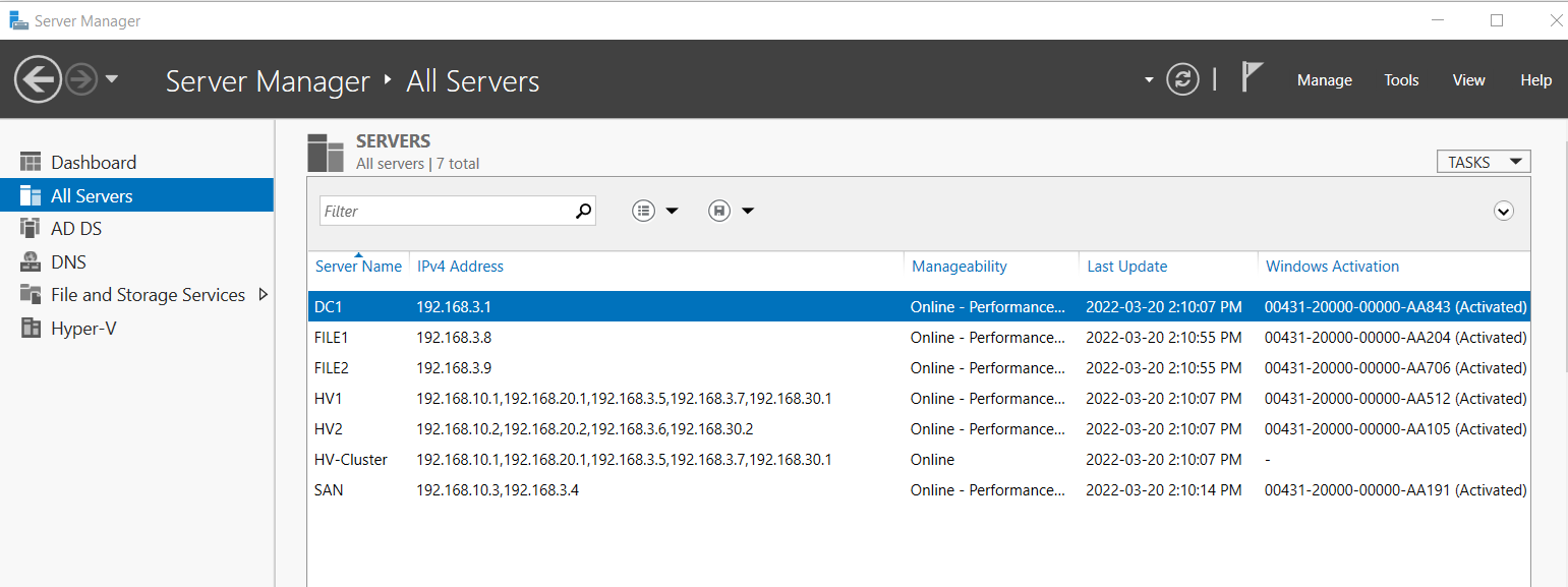
Capstone
| Date | |
|---|---|
| Project Type | Technology Support Professional (TSP) |
| By | Aidan Waugh |
Overview
Deliverables
From the laptop host Thinkpad complete the following:
- Configure a NAT/Firewall device
- Create and configure a DC
- Name the domain “cap.int”
- Have a domain joined Linux DHCP Server
- Have an Active Directory OU Structure
- Create and configure a SAN and have a disk that can tolerate 2 disk failures
- Configure 2 nested Hyper-V Servers that can Live Migrate VMs
- Create a File Server failover cluster within the nested Hyper-V
- Configure a file share with NTFS permissions
- Create Group Policies for mapped drives and folder redirection
- Create a secondary DC
Tables & Diagrams
Network Diagram
Network Diagram
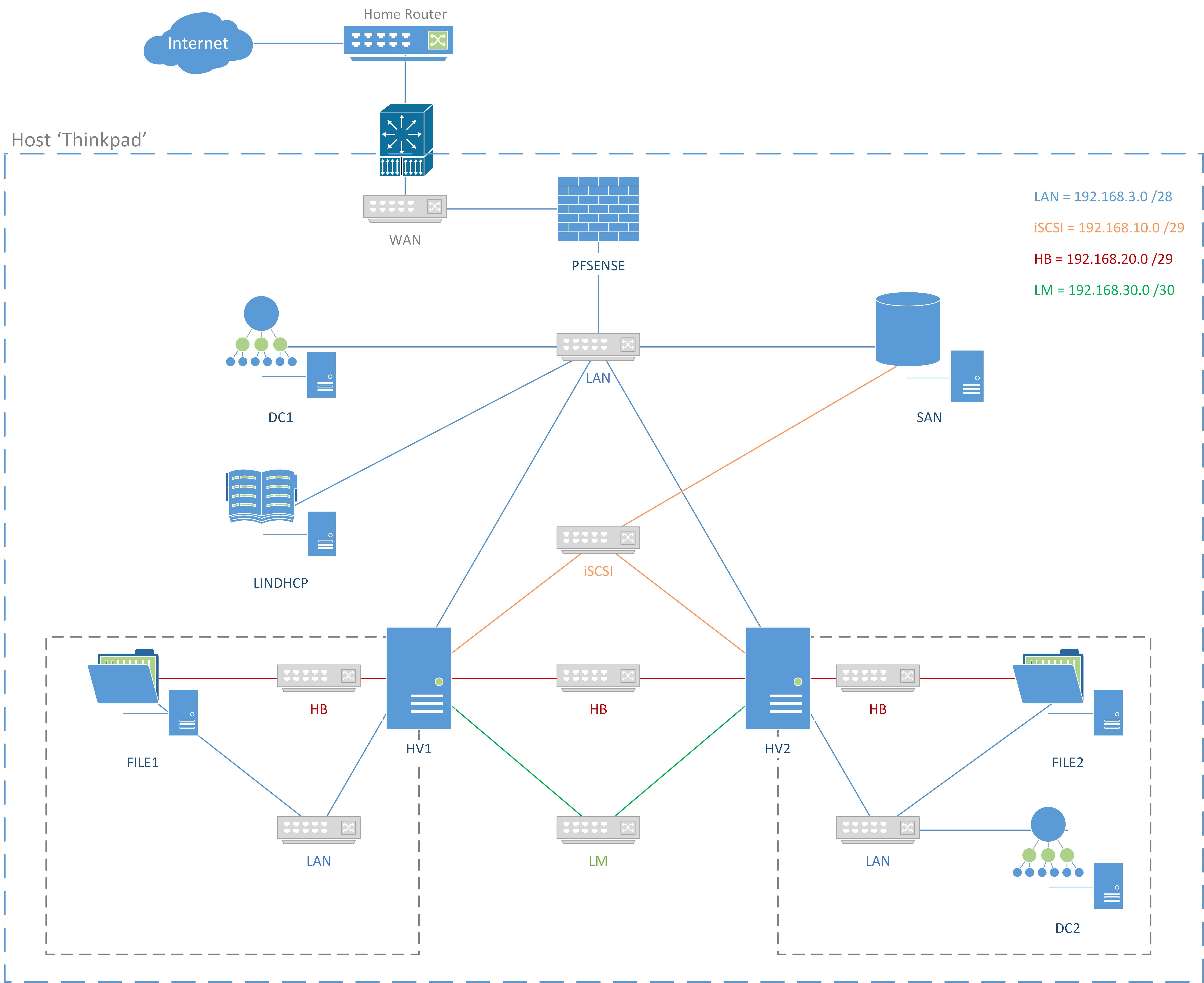
Network & IP Information
Network & IP Information
Networks
| Name | Network | Purpose | Subnet | Host IP Range | Switch Type |
|---|---|---|---|---|---|
| WAN | 192.168.1.0 /24 | Home Network | External | ||
| LAN | 192.168.3.0 /28 | LAN | 255.255.255.240 (/28) | 192.168.3.1 - 192.168.3.14 | Internal |
| iSCSI | 192.168.10.0 /29 | iSCSI SAN | 255.255.255.248 (/29) | 192.168.10.1 - 192.168.10.6 | Private |
| HB | 192.168.20.0 /29 | Heartbeat | 255.255.255.248 (/29) | 192.168.20.1 - 192.168.20.6 | Private |
| LM | 192.168.30.0 /30 | Live Migration | 255.255.255.252 (/30) | 192.168.30.1 - 192.168.30.2 | Private |
IP Addresses & Info
| Name | IP | RAM | Notes |
|---|---|---|---|
| DC1 | 192.168.3.1 /28 | 512 | |
| DC2 | 192.168.3.2 /28 | 512 | |
| LinDHCP | 192.168.3.3 /28 | 512 | |
| SAN | 192.168.10.3 /29192.168.3.4 /28 | 512 | |
| HV1 | 192.168.10.1 /29192.168.20.1192.168.3.5 /28192.168.30.1 | 4096 | \\192.168.3.5\d$ (before CSV)
\\192.168.3.5\c$\ClusterStorage\Volume1\ |
| HV2 | 192.168.10.2 /29192.168.20.2192.168.3.6 /28192.168.30.2 | 4096 | \\192.168.3.6\d$ (before CSV)
\\192.168.3.6\c$\ClusterStorage\Volume1\ |
| HV-Cluster | 192.168.3.7 /28 | ||
| FILE1 | 192.168.20.3192.168.3.8 /28 | 512 | |
| FILE2 | 192.168.20.4192.168.3.9 /28 | 512 | |
| FS-Cluster | 192.168.3.10 /28 | ||
| FS | 192.168.3.11 /28 | \\fs\Company_Data$ \\fs\HomeDir$ | |
| Thinkpad (Host) | 192.168.1.74 /24192.168.3.13 /28 | 16 GB (Host) | |
| pfSense | 192.168.1.10 /24192.168.3.14 /28 | 512 |
cap.int Domain ADDS Diagram
cap.int Domain ADDS Diagram

Server File & Storage Diagram
Server File & Storage Diagram

1.0 Setup
The host Thinkpad is a Type I Hypervisor with 16GB RAM. Download all operating system files for the virtual machines (Windows Server 2019, pfSense, CentOS 8) and sysprep Windows Server 2019 Core to save time and hard disk space. Create the network switches to allow for a local area network (LAN), iSCSI, heartbeat (HB) for file servers, and live migration (LM) of virtual machines.
1.0 Download ISO Files
1.0 Download ISO Files
- Windows Server 2019 ISO for DC1, DC2, SAN, FILE1, FILE2, HV1, HV2 as Server Core
- pfSense for NAT and Firewall
- CentOS 8 Stream x86_64-latest-dvd1.iso for the Linux DHCP server
1.2 Sysprep Windows Server 2019 - Core
1.2 Sysprep Windows Server 2019 - Core
- In Hyper-V create a new VM named “ParentServer2019-Core” with 4096 MB of memory
- Turn off the VM’s automatic checkpoints
- Connect and start the VM
- Install Windows Server Datacenter (without Desktop Experience) then reboot
- Set a admin password
- Enter PS by typing
powershell
- From PowerShell open the System Preparation Tool (Sysprep) with:
cd C:\Windows\System32\Sysprep\
ls
.\sysprep.exe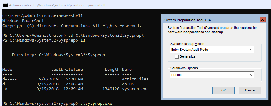
- Set SysPrep to the following:
- System Cleanup Action: Enter System Audit Mode
- Generalize: unchecked
- Shut down options: Reboot
- Install all updates by entering
sconfig> type6To Download an Install Updates
- Reboot the VM
- Set SysPrep to the following:
- System Cleanup Action: Enter System Out-of-Box Experience (OOBE)
- Generalize: Checked
- Shut down options: Shutdown
- Delete the ParentServer2019-Core VM from Hyper-V and make the vhdx file read only
- Create a VM on the host with the differencing disk by either:
- Option 1: In Hyper-V, create a new differencing hard disk > create a new VM and attach the child vhdx
- Option 2: Use the following script:
#
# Create a VM with Windows Server 2019 (Core) with 2GB Static Memory on a Differencing Disk
# Connect to the LAN switch
# Disable automatic checkpoints & enable VM Guest Services
#
$VMName = Read-Host -Prompt 'Input the VM name'
$parentpath = "V:\VMs\VHDX\ParentServer2019-Core.vhdx"
$VHDPath = "V:\VMs\VHDX\" + $VMName + ".vhdx"

# Create VM with a differencing disk, update settings ,and start vm
New-VHD -ParentPath $parentpath -Path $VHDPath -Differencing
New-VM -Name $VMName -MemoryStartupBytes 2GB -VHDPath $VHDPath -Generation 2 -SwitchName LAN
Set-VM $VMName -AutomaticCheckpointsEnabled $false
Set-VMMemory $VMName -DynamicMemoryEnabled $false
Enable-VMIntegrationService -VMName $VMName -Name "Guest Service Interface"
Start-VM -Name $VMName
VMConnect.exe
1.3 Create Virtual Switches in Hyper-V
1.3 Create Virtual Switches in Hyper-V
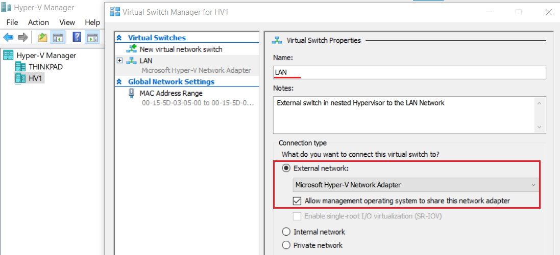
- From the host’s (Thinkpad laptop) Hyper-V Manager > click Virtual Switch Manager...
- Click new virtual network switch > and create the following:
Switch Name Switch Type Notes WAN External LAN Internal 192.168.3.0 /28 → 14 hosts, 16 IPs 192.168.3.1 - 192.168.3.14 iSCSI Private iSCSI SAN: 192.168.10.0 /29 → 6 hosts, 8 IPs 192.168.10.1 - 192.168.10.6 HB Private FS cluster heartbeat 192.168.20.0 /29 → 6 hosts, 8 IPs 192.168.20.1 - 192.168.20.6 LM Private Live Migration192.168.30.0 /30 → 2 hosts, 4 IPs 192.168.30.1 - 192.168.30.2 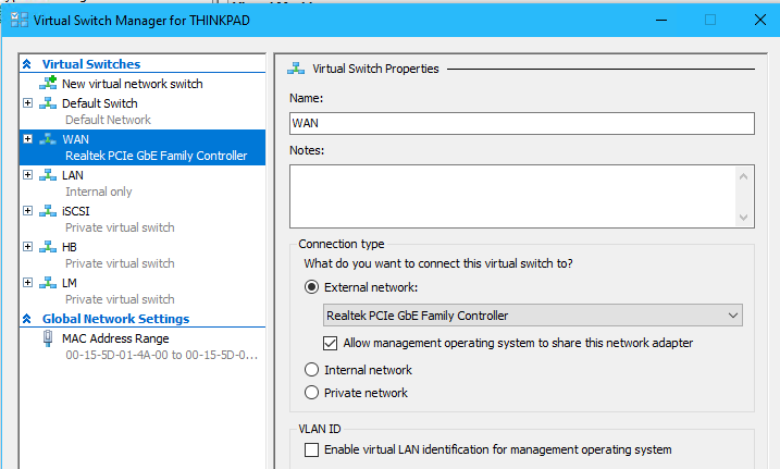
- (Optional) Go to the host’s Network Connections > view the adapter properties
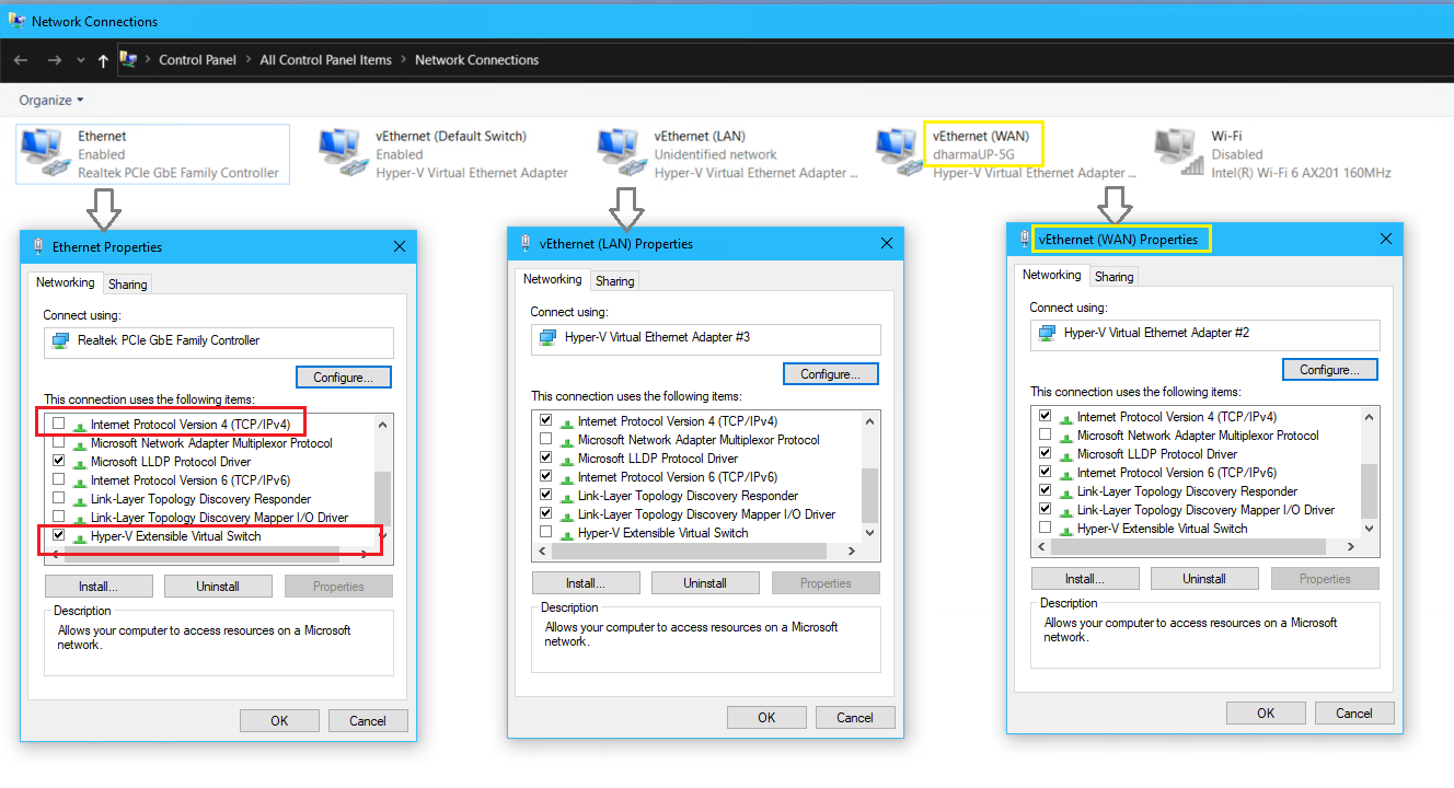
The host’s adapter became a Hyper-V Extensible virtual switch and the previous settings migrated to vEthernet WAN upon the external virtual switch creation
- (Optional) on the host, enter
ipconfig /all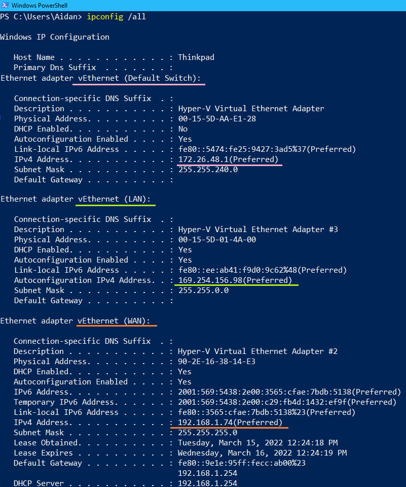
1.4 Set IP Addressing Values on Home Router (Optional)
1.4 Set IP Addressing Values on Home Router (Optional)
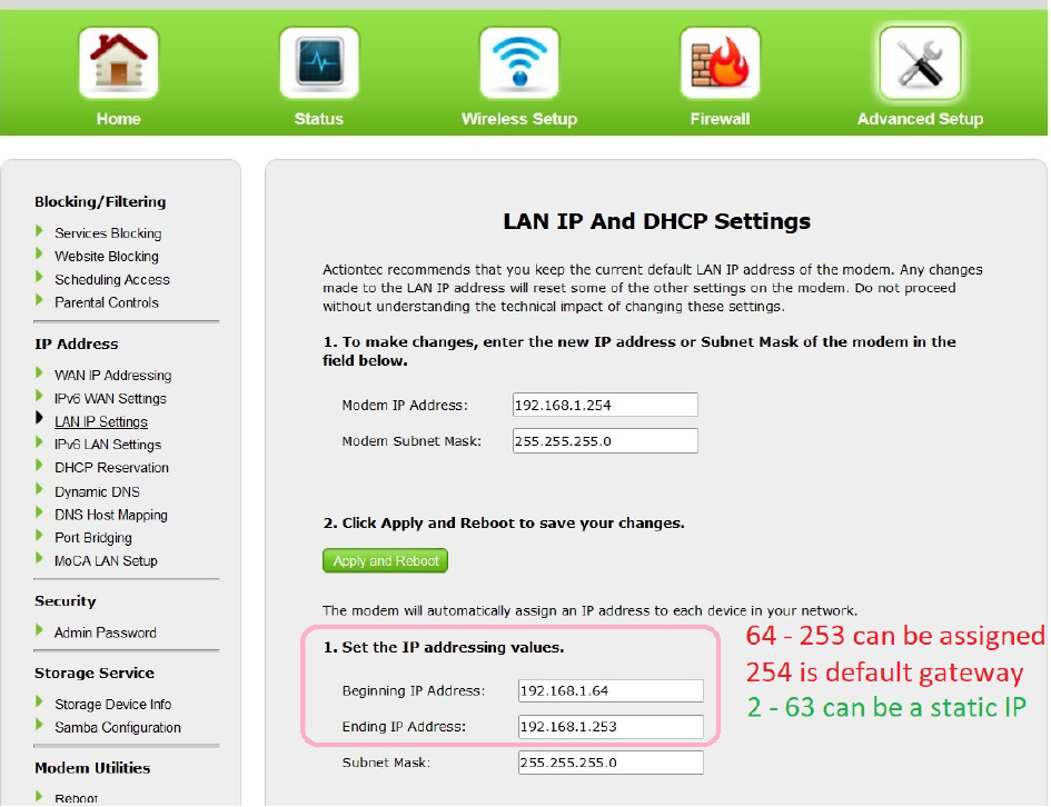
- From a web browser on the host machine go to
192.168.1.254and login
- Set a IP addressing range for DHCP and make note of the excluded range
2.0 pfSense NAT & Firewall
Create a OpenBSD NAT/Firewall Router with pfSense on the WAN network. The network LAN has double NAT as the physical home router is the first. Create firewall rules to block HV1, HV2, SAN and DC2 from accessing the internet.
2.1 Create the VM and Install pfSense
2.1 Create the VM and Install pfSense
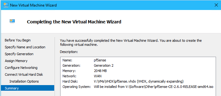
- Create a VM named “pfSense” with the following:
- Name: “pfSense”
- Generation: Generation 2
- Memory: 2048 MB Dynamic (this will be set to 512 MB Static after configuration is complete)
- Network: WAN
- Hard Disk: 40GB Dynamic Expanding
- Operating System: pfSense.iso
- Right click the pfSense VM > select Settings... > Edit the following:
- Security: Uncheck Enable Secure Boot
- Checkpoints: Uncheck Use Automatic Checkpoints
- Click Add Hardware > Network Adapter > Virtual Switch: select LAN
- In Hyper-V right-click on the pfSense VM > Connect... > click Start
- Use the arrow keys to navigate, SPACE to toggle and ENTER to select
- Complete the installation with the following:
- Copyright and Trademark Notice > Accept
- Welcome to pfSense: Select Install > Install pfSense > OK
- Keymap Selection: Leave the default option Continue with default keymap as is> Select
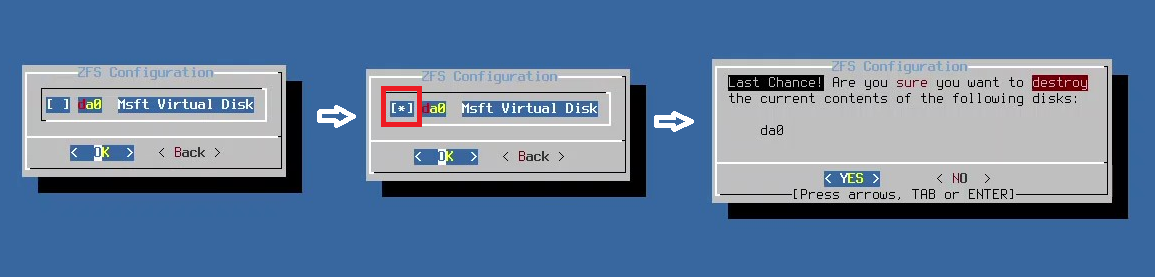
- Partitioning: Leave the default Auto (ZFS) Guided Root-on-ZFS selected > OK
- Configure options: Install Proceed with Installation > Select
- Select Virtual Device Type: Select Stripe - No Redundancy > OK
- ZFS Configuration: Press the Space Bar to select the Msft Virtual Disk > OK
- Select YES when asked to destroy the da0 disk
- The distribution files will extract and install
- When asked to make any final manual modifications when the installation is finished, select YES
- From the shell type
poweroff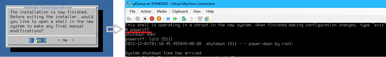
poweroffstops the VM from rebooting off the iso file in a continuous loop
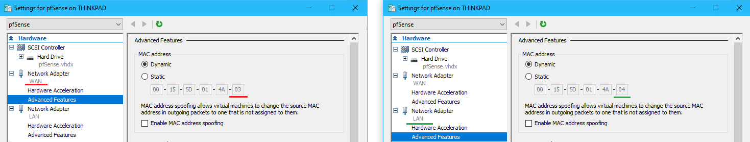
- Open the Hyper-V settings for pfSense
- Click Firmware > Select the Hard Drive pfSense.vhdx and move up to become first in the boot order
- Click SCSI Controller > DVD Drive > Remove the pfsense.iso file
- Expand the WAN Network Adapter > Click Advanced Features > View the MAC Address
- Expand the LAN Network Adapter > Click Advanced Features > View the MAC Address
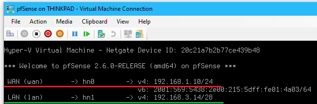
2.2 Configure WAN and LAN Interfaces on pfSense
2.2 Configure WAN and LAN Interfaces on pfSense
- Start the pfSense VM
- View the valid interfaces
hn0andhn1and notice the last hexadecimal digit (hn0 = 03 → WAN network adapter)
- Configure the interface’s for WAN
hn0and LANhn1with the following:- Do VLANS need to be setup now? >
n
- Enter the WAN interface name >
hn0
- Enter the LAN interface name >
hn1
- Do you want to proceed? >
yto write configuration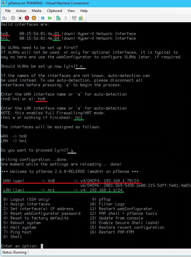
- Do VLANS need to be setup now? >
- Set the LAN interface IP to
192.168.3.14 /28by selecting option2and entering the following:- Enter the number of the interface you wish to configure >
2
- Enter the new LAN IPv4 address >
192.168.3.14
- Enter the new LAN IPv4 subnet bit count >
28
- For a WAN, enter the new LAN IPv4 upstream gateway address > press ENTER for none
- Enter the new LAN IPv6 address > press ENTER for none
- Do you want to enable the DHCP server on LAN? >
y
- Do you want to revert to HTTP as the webConfigurator protocol? >
y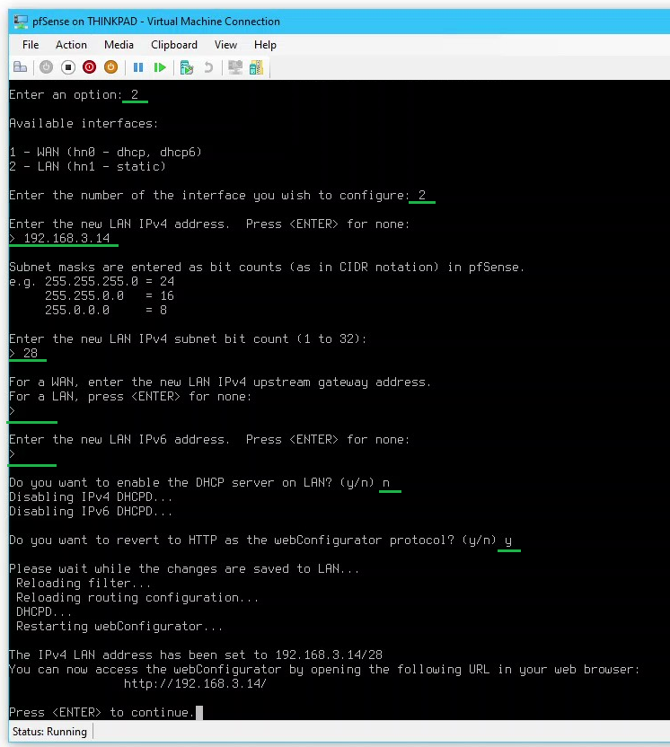
- Enter the number of the interface you wish to configure >
- (Optional) Set the WAN interface IP to
192.168.1.10 /24by selecting option2and entering the following:- Enter the number of the interface you wish to configure >
1
- Enter the new LAN IPv4 address >
192.168.1.10
- Enter the new LAN IPv4 subnet bit count >
24
- For a WAN, enter the new LAN IPv4 upstream gateway address >
192.168.1.254
- Enter the new LAN IPv6 address > press ENTER for none
- Enter the number of the interface you wish to configure >
2.3 Test Networking
2.3 Test Networking
- On the Thinkpad host, go to the vEthernet (LAN) network adapter > Properties > IPv4
- Set a static IP of
192.168.3.13with a subnet mask255.255.255.240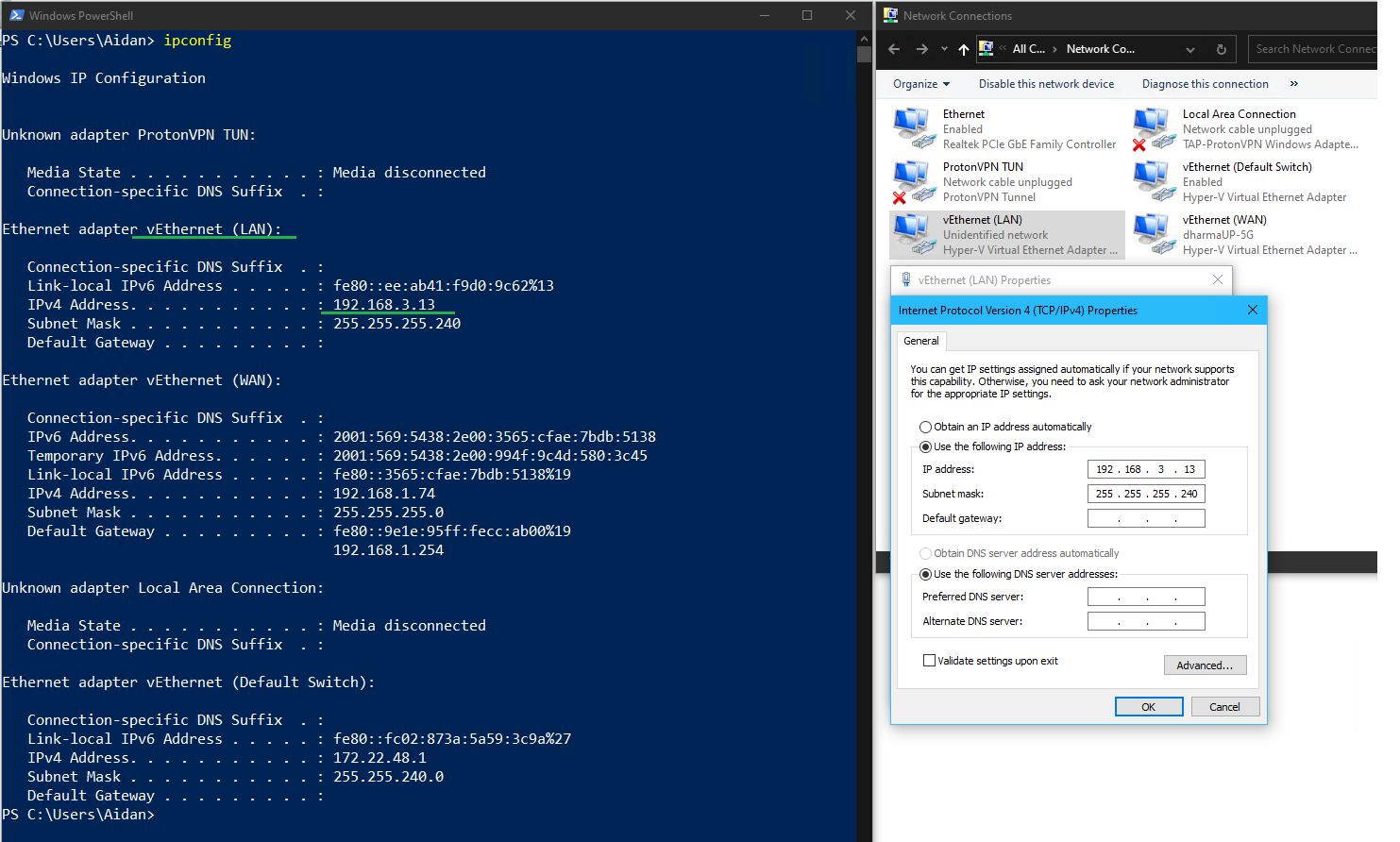
- From pfSense, selecting option
7to ping the following hosts:google.ca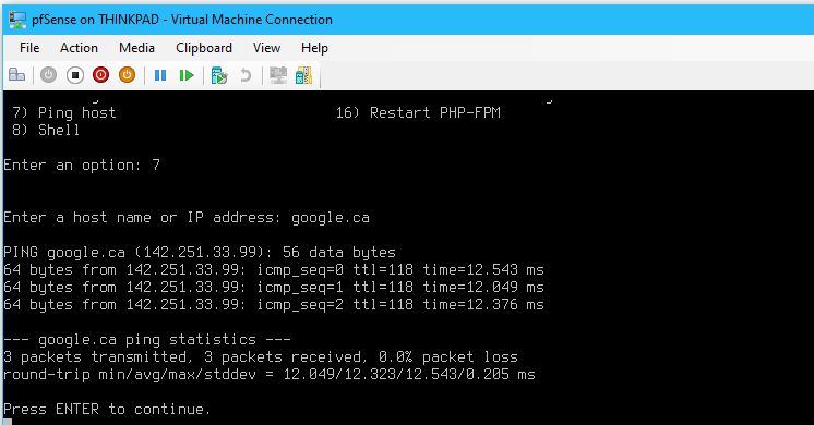
- Thinkpad Host WAN
192.168.1.74& LAN192.168.3.13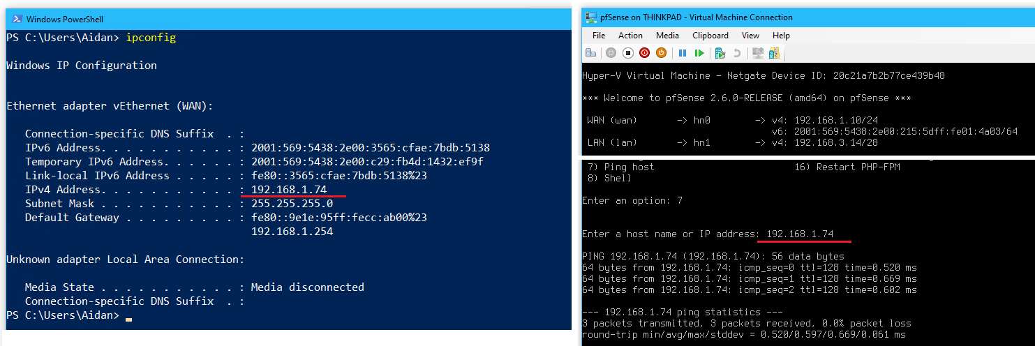
WAN 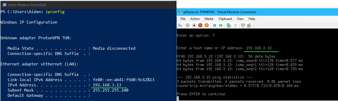
LAN
- From Host Thinkpad ,
ping 192.168.3.14the LAN interface on pfSense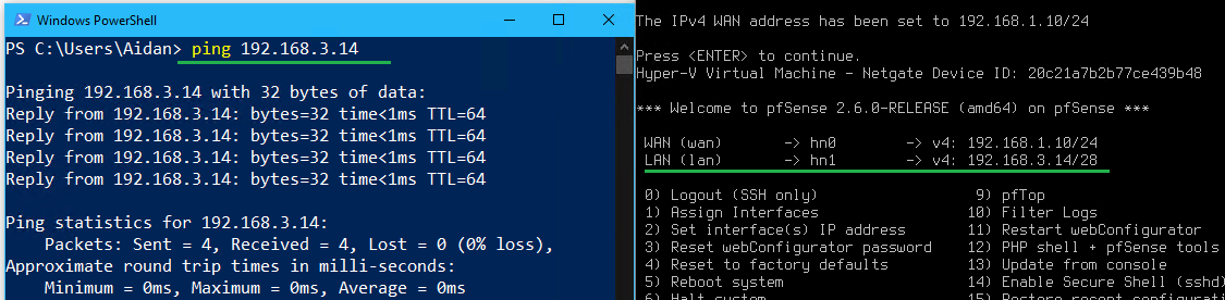
2.4 Mange pfSense from the web GUI
2.4 Mange pfSense from the web GUI
- From the host Thinkpad, go to a web browser and enter
192.168.3.14in the address bar
- Enter the default pfSense credentials to login
- Username:
admin
- Password:
pfsense
- Username:
- Complete the 9 steps in the Wizard / pfSense Setup
- Step 1 - Netgate Global support: > Click Next
- Step 2 - General Information: Leave the hostname, domain, and DNS settings as is > Next
- Step 3 - Time Server Information: Select timezone US/Pacific > Next
- Step 4 - Configure WAN Interface: Leave DHCP Selected Type as Static > Next
- Step 5 - Configure LAN interface: Leave the LAN IP address and subnet mask as
192.168.3.14 /28> Next
- Step 6 - Set Admin webGUI Password: Enter
Pa$$w0rdas the new admin password > Next
- Step 7 - Reload Configuration: Click Reload
- Step 8 - Reload in progress: Wait for the reload to finish
- Step 9 - Wizard completed: Click Check for Updates
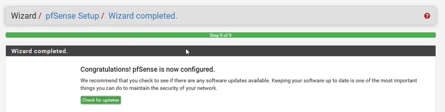
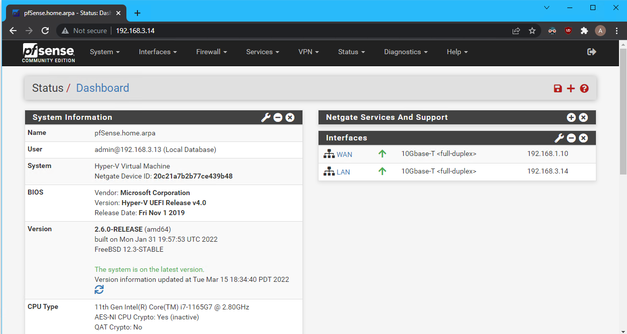
- View the pfSense dashboard
2.5 Configure Firewall Rules
2.5 Configure Firewall Rules
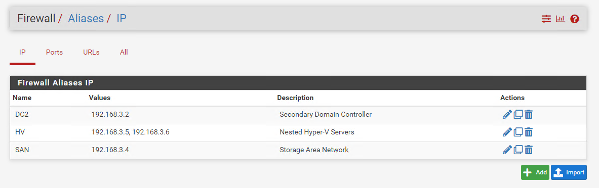
- From the pfSense Web GUI go to the Firewall tab > click Aliases
- Click New to make a alias for both nested Hyper-V Servers
- Name: ‘HV’
- Type: Select Hosts
- IP:
192.168.3.5and192.168.3.6
- Click Save
- Repeat for SAN 192.168.3.4 & DC2 192.168.3.2
- Go to Firewall > Rules > click LAN
- Click Add to create a new firewall rule to block the alias HV from reaching the internet with the following:
- Action: Select Block
- Protocol: Select Any
- Address Family: IPv4+IPv6
- Source: Select Single host or alias > HV
- Destination: Select Any
- Click Save
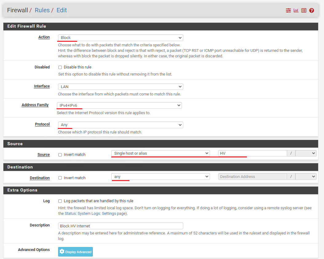
- Repeat for Alias SAN and DC2
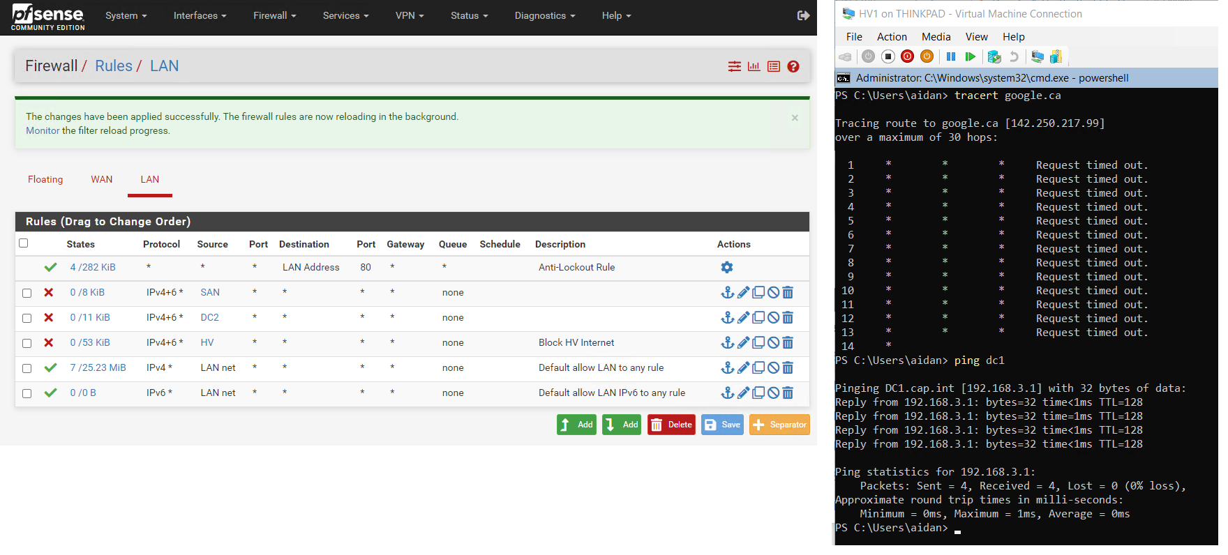
End result when VMs are created and the firewall rules are enabled
- Disable all of the firewall rules while the network infrastructure is being created
- In Hyper-V, set the RAM for pfSense to 512 MB Static
- ⏲ Take a checkpoint of pfSense named “FW configuration complete”
3.0 Domain Controller
In Windows Server 2019 core, create a DC and a domain named “cap.int” with all the data stored on a secondary disk. Make a domain administrator account aidan@cap.int which will be used for the rest of the project.
3.1 Create VM DC1
3.1 Create VM DC1
- On the host Thinkpad and open PowerShell as an administrator and run the script below to create a VM with the following properties:
- Name: DC1
- Generation: Generation 2
- Memory: 2048 MB Static (this will be set to 512 MB Static after configuration is complete)
- Network: LAN
- Hard Disk: Differencing disk to ParentServer2019-Core.vhdx
- Operating System: Windows Server 2019 (Core)
- Automatic Checkpoints: Disabled
- VM Guest Services: Enabled
#
# Create a VM with Windows Server 2019 (Core) with 2GB Static Memory on a Differencing Disk
# Connect to the LAN switch
# Disable automatic checkpoints & enable VM Guest Services
#
$VMName = Read-Host -Prompt 'Input the VM name'
$parentpath = "V:\VMs\VHDX\ParentServer2019-Core.vhdx"
$VHDPath = "V:\VMs\VHDX\" + $VMName + ".vhdx"

# Create VM with a differencing disk, update settings ,and start vm
New-VHD -ParentPath $parentpath -Path $VHDPath -Differencing
New-VM -Name $VMName -MemoryStartupBytes 2GB -VHDPath $VHDPath -Generation 2 -SwitchName LAN
Set-VM $VMName -AutomaticCheckpointsEnabled $false
Set-VMMemory $VMName -DynamicMemoryEnabled $false
Enable-VMIntegrationService -VMName $VMName -Name "Guest Service Interface"
Start-VM -Name $VMName
VMConnect.exe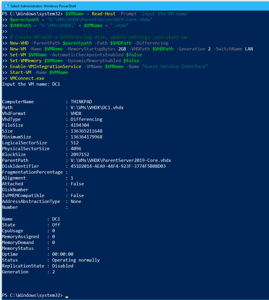
- Enter
Pa$$w0rdas the new credentials for Administrator
3.2 Server Configuration with sconfig
3.2 Server Configuration with sconfig
- On DC1 open Server Configuration by entering
sconfig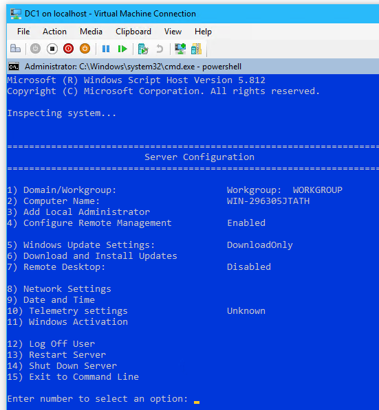
- Select
8to edit Network Settings
- Select option
1to Set Network Adapter Address- Select:
sfor Static IP
- Enter Static IP address:
192.168.3.1
- Enter Subnet Mask:
255.255.255.240
- Enter Default Gateway:
192.168.1.14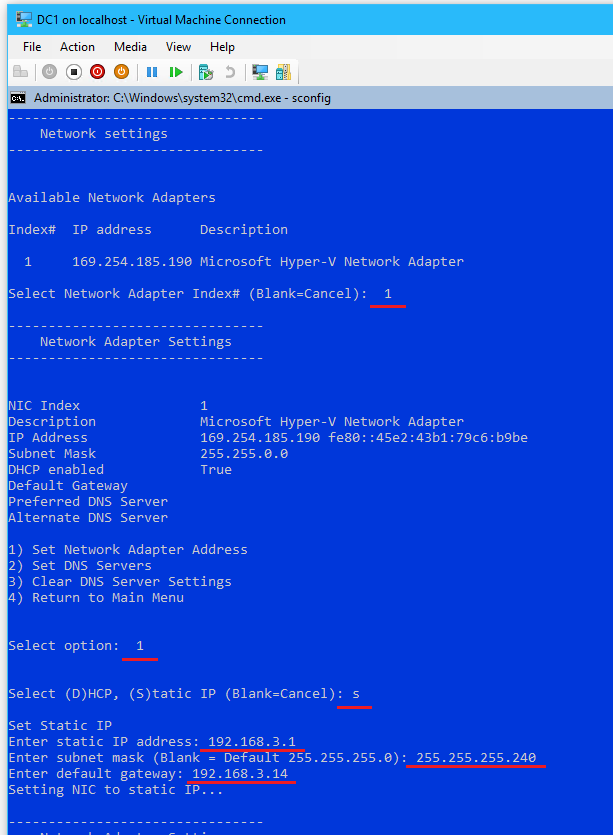
- Select:
- From the Network Adapter Settings options, select option
2to set DNS Servers > enter new preferred DNS server:8.8.8.8
- From the Server Configuration options, select option
15to Exit to Command Line
- Type
powershell
- Test network connectivity with:
ping google.ca
ping 192.168.3.14(pfSense)
ping 192.168.3.13(Thinkpad Host)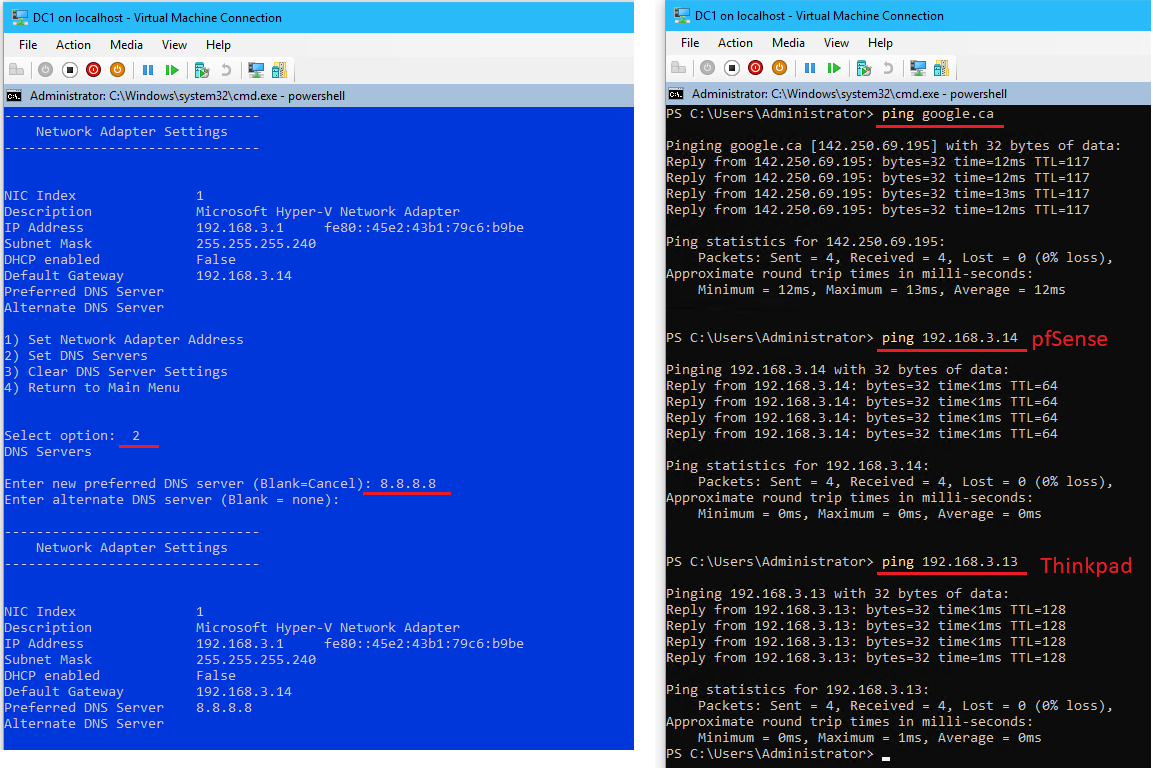
tracert google.ca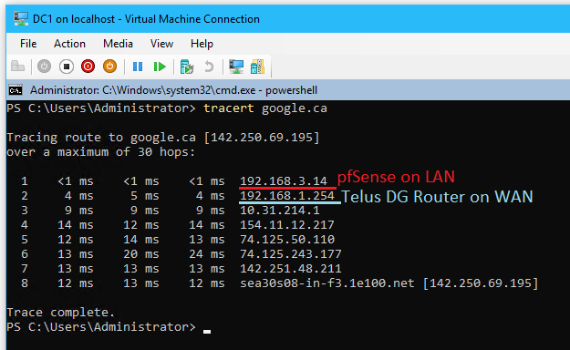
- Return to Server Configuration with
sconfig
- Download and install updates by selecting option
6- Search for all updates with
A
- Install all updates with
A
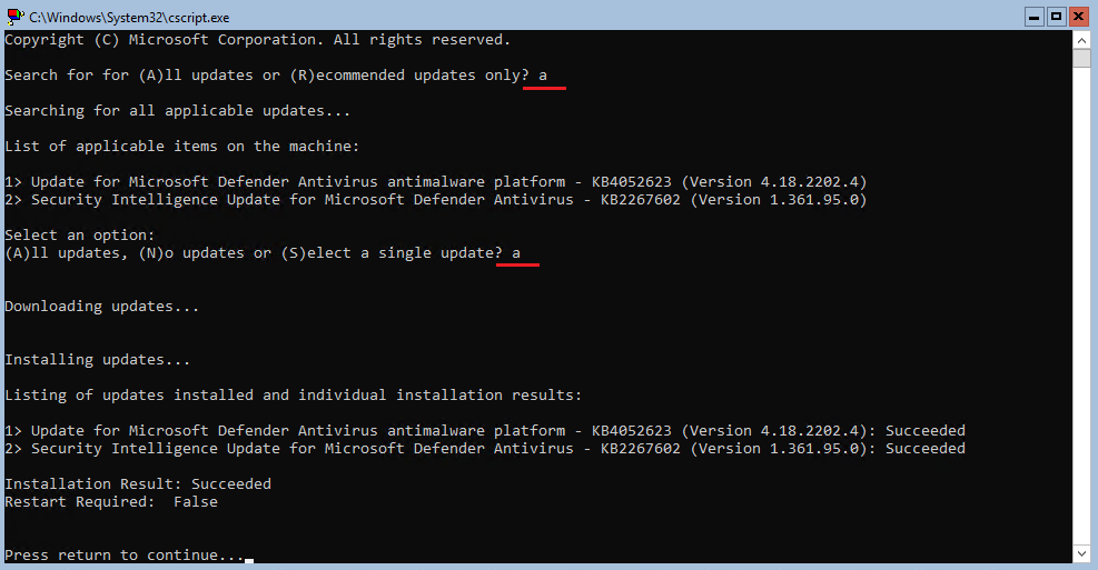
- Search for all updates with
- From Server Configuration, select option
11for Windows Activation- Select
2to Activate Windows
- Select
1to Display License Info
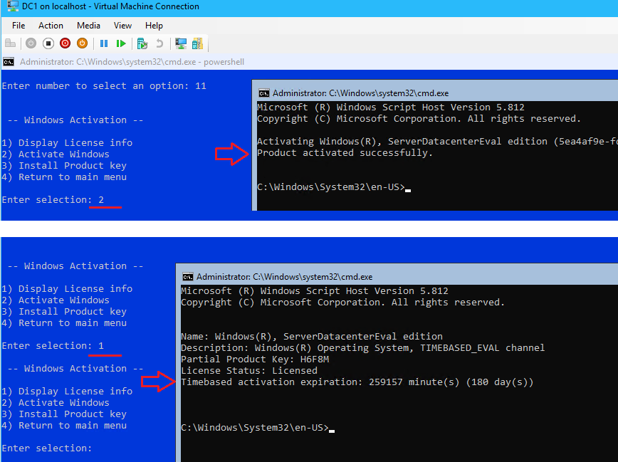
Server Trial gives 180 days - Select
- From Server Configuration, select option
2to change the computer name to “DC1”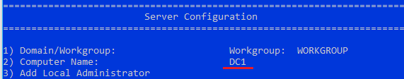
- Restart the server with option
13to apply the name change
3.3 Configuration with PowerShell
3.3 Configuration with PowerShell
- Enter PowerShell on DC1 with
powershell
- Rename the local user account Administrator to “_sysadmin” with the following:
Get-LocalUser
Rename-LocalUser -Name "Administrator" -NewName "_sysadmin"
#View changes
Get-LocalUser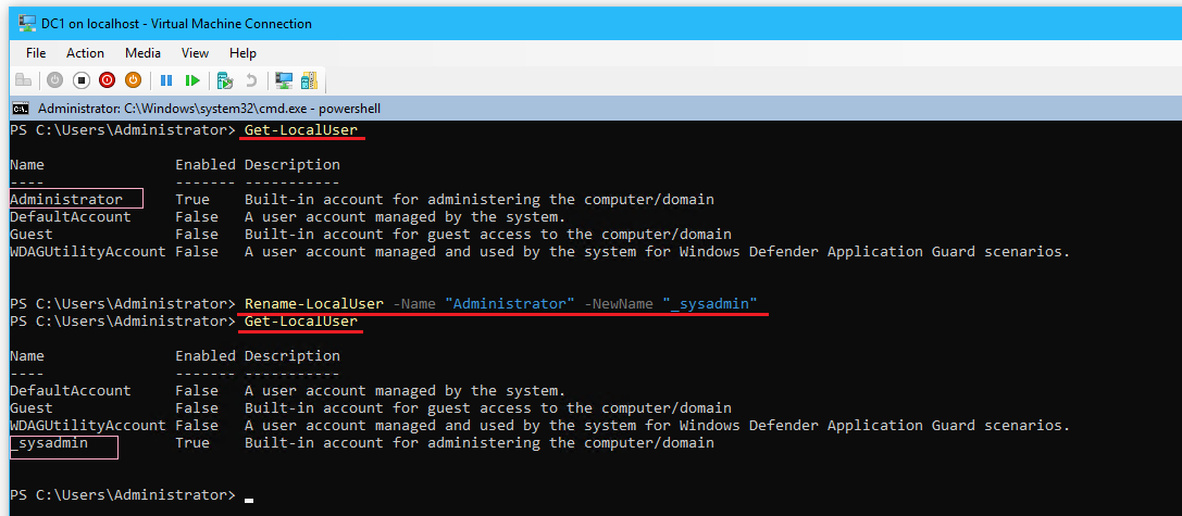
- Log off as user Administrator with
sconfig> Select option12
- Log into DC1 with the user _sysadmin
- Open
powershell
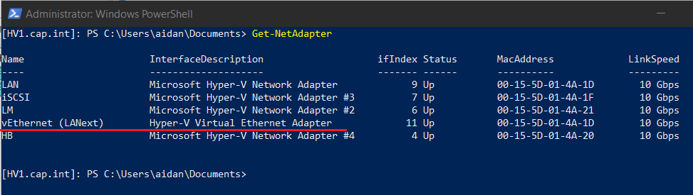
- Rename the network adapter from Ethernet to “LAN” with the following:
Get-NetAdapter
Rename-NetAdapter -Name "Ethernet" -NewName "LAN"
Get-NetAdapter

#To view additional properties of the adapter (can omit -Name or -Property)
Get-NetAdapter -Name "LAN" | Format-List -Property *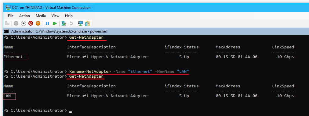
For VM’s that have multiple adapters, view the MAC Address in Hyper-V and reference the -Name or -ifIndex
- In Hyper-V, create and attach a 10 GB Dynamically expanding VHDX named
DC1dbto DC1
- From
powershellon DC1 initialize, partition, and format the volume with the following:Get-Disk Initialize-Disk -Number 1 New-Partition -DiskNumber 1 -UseMaximumSize Get-Partition -DiskNumber 1 Get-Partition -DiskNumber 1 -PartitionNumber 2 | Format-Volume -FileSystem NTFS Get-Partition -DiskNumber 1 -PartitionNumber 2 | Set-Partition -NewDriveLetter D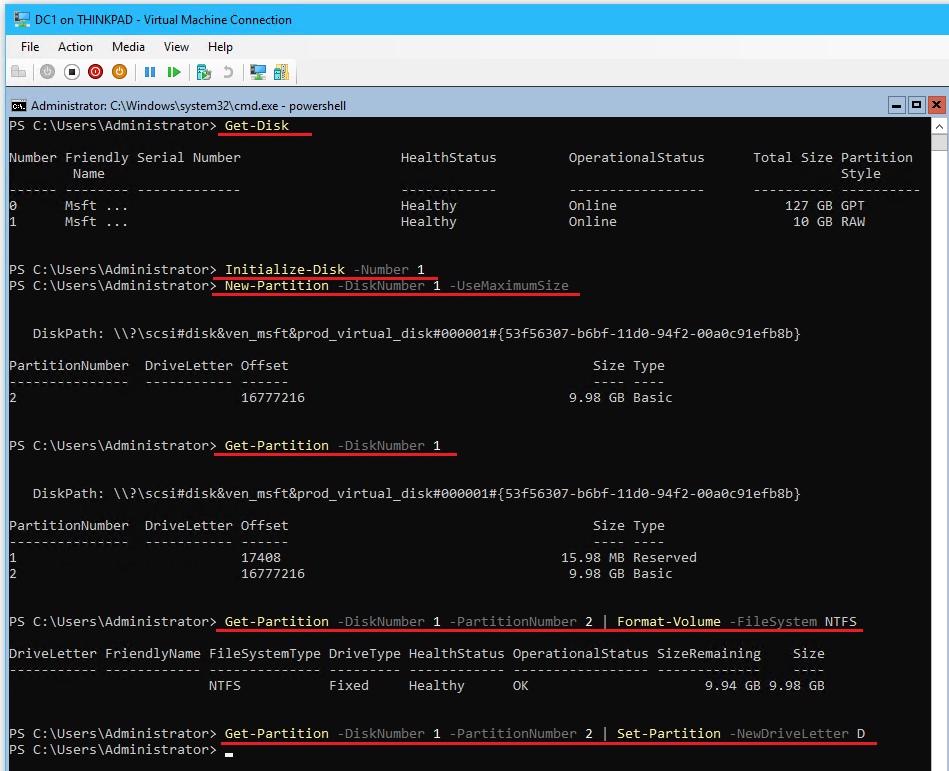
- Create directories ‘SYSVOL’ and ‘NTDS’ in the new volume
D:\withmd SYSVOL&md NTDS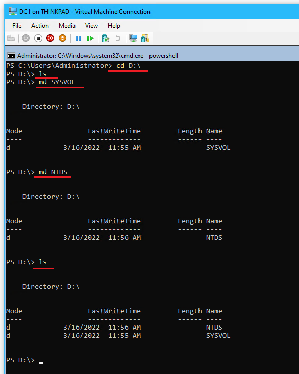
- ⏲ Checkpoint DC1 & name it “Before AD Role”
3.3 Add AD DS Role
3.3 Add AD DS Role
- From PowerShell DC1, install the Active Directory Domain Services role with the following:
#Install ADDS and Group Policy Management Console (GPMC)
Install-WindowsFeature -Name AD-Domain-Services,GPMC -IncludeManagementTools -Verbose

#Make sure that the AD-Domain-Services role is installed
Get-WindowsFeature -Name *AD*

#use ADDSDeployment module cmdlets to deploy a new domain
Get-Command -Module ADDSDeployment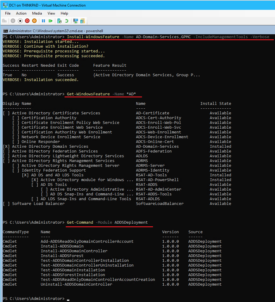
- ⏲ Checkpoint DC1 with the name “Before new domain”
- From PowerShell create a new forest root domain
cap.intwith the following:# # Windows PowerShell script for AD DS Deployment # Install-ADDSForest: Installs a new forest root domain # Import-Module ADDSDeployment Install-ADDSForest ` -DatabasePath "D:\NTDS" ` -DomainMode "WinThreshold" ` -DomainName "cap.int" ` -DomainNetbiosName "cap" ` -ForestMode "WinThreshold" ` -InstallDns:$true ` -LogPath "D:\NTDS" ` -NoRebootOnCompletion:$false ` -SysvolPath "D:\SYSVOL" ` -Force:$true #Enter Pa$$w0rd as the SafeModeAdministrator password
- Reboot the DC1 server (may take up to 10 minutes on first reboot) and login with userPrincipleName (UPN)
_sysadmin@cap.intorcap\_sysadmin- ❗ To change the user, have the VM connection in ‘Basic Session’ and hit the ESC key twice
- (Optional) Verify the successful installation of the services in PowerShell
# List the status of the AD related services on DC
Get-Service adws,kdc,netlogon,dns

# List configuration details of the DC
Get-ADDomainController

# List details of Active Directory Domain
Get-ADDomain cap.int

# List Active Directory Forest details
Get-ADForest cap.int
- ⏲ Checkpoint DC1 and name it “Before Aidan Admin Creation”
3.4 Create Domain Administrator aidan@cap.int
3.4 Create Domain Administrator aidan@cap.int
- In PowerShell, create a new User named “Aidan” & copy the properties of _sysadmin
Import-Module ActiveDirectory

#Create new Active Directory User
New-ADUser `
-Name "Aidan" `
-GivenName "Aidan" `
-Surname "Waugh" `
-SamAccountName "Aidan" `
-UserPrincipalName "Aidan@cap.int" `
-AccountPassword (ConvertTo-SecureString "Password123" -AsPlainText -Force) `
-ChangePasswordAtLogon $true `
-Enabled $true

#View User Details (Optional)
Get-ADUser -Identity Aidan -Properties *

#Copy _Sysadmin's property "Member of"
$getusergroups = Get-ADUser –Identity _sysadmin -Properties memberof | Select-Object -ExpandProperty memberof

#Assign Aidan to be a member of the same groups > become a domain admin
$getusergroups | Add-ADGroupMember -Members Aidan -verbose

#Verify
Get-ADUser -Identity Aidan -Properties memberof | Select-Object -ExpandProperty memberof
- Login to DC1 with the aidan@cap.int account
- ⏲ In Hyper-V, delete the checkpoint subtree on DC1
- ⏲ Checkpoint DC1 and name it “Before Thinkpad joins domain”
4.0 Add Host Thinkpad to the Domain
Join the host Thinkpad to the cap.int domain. As all Windows Servers are core, accessing Server Core from a domain joined machine will allow configuration with a graphical user interface. If enough memory is on the host machine, create a Windows 10 VM insead.
4.1 Join Thinkpad to the cap.int Domain
4.1 Join Thinkpad to the cap.int Domain
- Set the LAN vEthernet adapter DNS settings to
192.168.3.1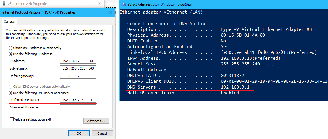
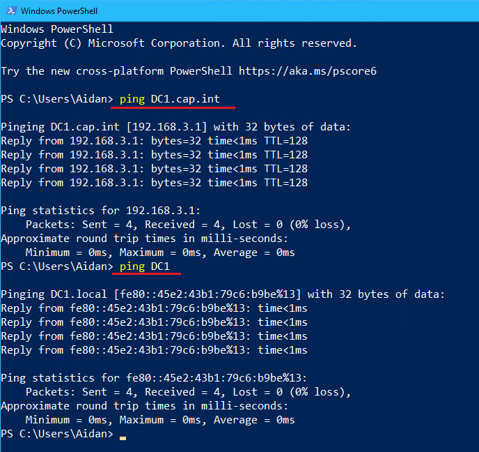
- Verify that DC1 can be found
- On Thinkpad right-click the Windows Icon > System and view the About Page
- Click Rename this PC (advanced) > click Change...
- In the popup Computer Name/Domain Changes complete the following:
- Domain:
cap.int
- Credentials:
aidan@cap.int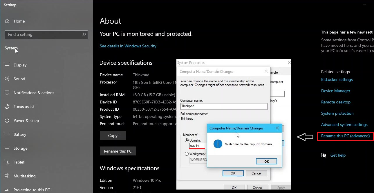
- Domain:
- Restart Thinkpad
- ❗ Note - as Thinkpad is a Type 1 Hypervisor, any VM’s that are running will restart when the host does. And can be accessed from any account thinkpad\aidan or cap\aidan
- Log into the local user account thinkpad\aidan
- Reboot & log into thinkpad\aidan
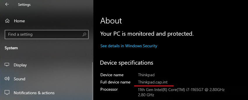
- View the computer name from Settings > About and notice that the full device name is now thinkpad.cap.int
- Switch user and log into cap\aidan. If using RDP to access Thinkpad, enter cap\aidan as the new credentials.
- View the networking - the IP’s are the same
- Open Hyper-V and notice that the VMs are present
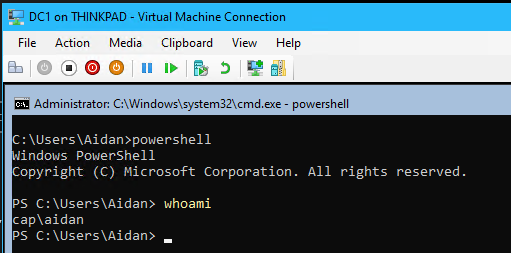
- ❗ The rest of the project should be completed on Thinkpad logged in as the domain administrator cap\aidan. Errors will occur if working from the local computer account even when the domain credentials are used.
4.2 Access DC1 from Server Manager on Thinkpad
4.2 Access DC1 from Server Manager on Thinkpad
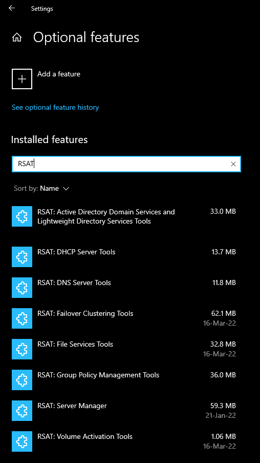
- On Thinkpad search for “Optional Features” > click Add a feature > Install the following Remote Server Administration Tools (RSAT) tools:
- Open Server Manager
- In the toolbar click Manage > Add Servers
- Select the DNS tab > search for
dc1& select > click OK to add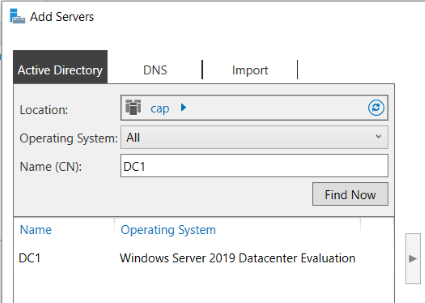
Logged in as cap\aidan 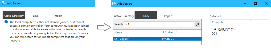
If using the local thinkpad\aidan account, servers can not be found with the Active Directory tab
- If using the local thinkpad\aidan account (not recommended), right click server DC1 > select Manage as... > Enter domain admin credentials
aidan@cap.int
“Manage as...” removes the Kerberos error. This does not occur from cap\aidan
5.0 Configure DNS on DC1
The forward lookup zone is setup automatically and sets the forwarders during the domain creation from -InstallDns:$true however, the reverse lookup zone needs to be created and configured.
5.1 Forward and Reverse Lookup Zones
5.1 Forward and Reverse Lookup Zones
- In Server Manager’s left panel, click on DNS
- Right click DC1 > Select DNS Manager
- From DNS Manager, right click DC1.cap.int > Properties > Open the Forwarders tab
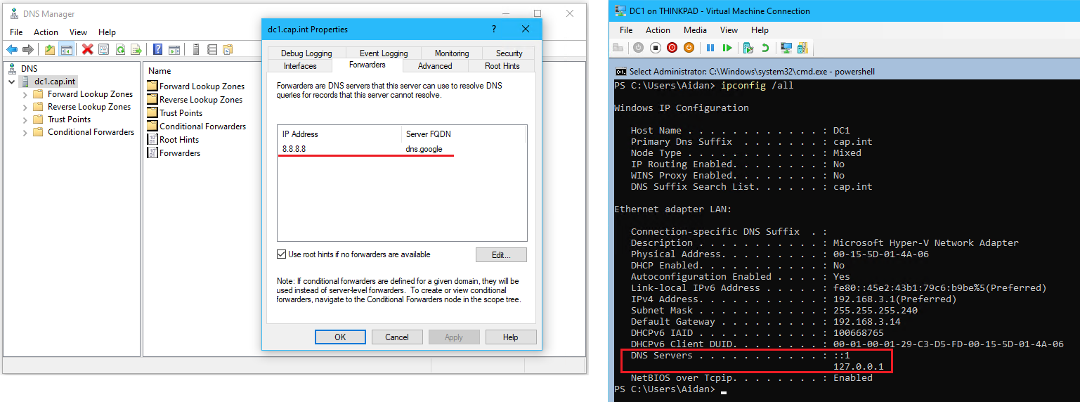
The previous DNS address 8.8.8.8is now set as the forwarder & the DC1 Interface DNS points to itself. This was all done automatically during the DNS installation with -InstallDns:$true
- Navigate to Forward Lookup Zones and click on cap.int to view the existing entries
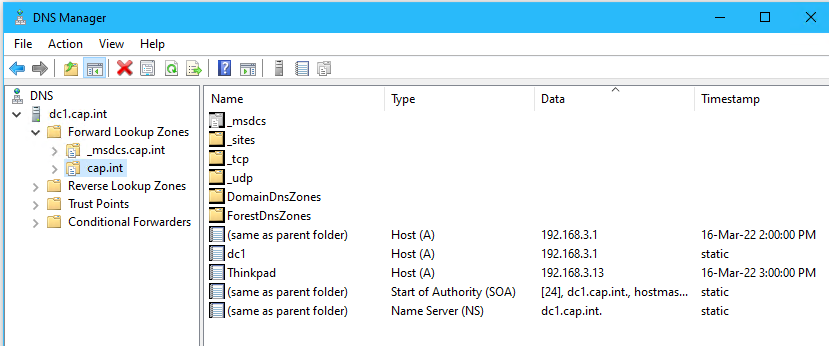
The Forward Lookup Zone does not need to be configured
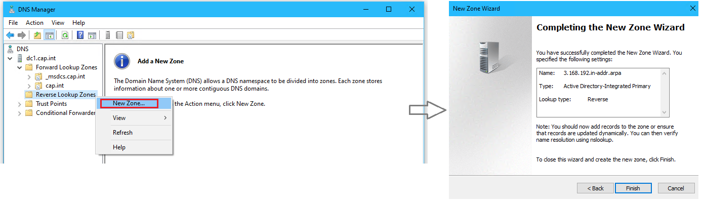
- Right click the directory Reverse Lookup Zones > select New Zone.. to open the Wizard
- Complete the New Zone Wizard with the following:
- Zone Type: Primary Zone
- Active Directory Zone Replication Scope: To all DNS servers running on domain controllers in this domain: proj.int (2nd option)
- Reverse Lookup Zone Name: IPv4 Reverse Lookup Zone
- Network ID:
192.168.3
- Dynamic Update: Allow only secure dynamic updates (1st option which is recommended for Active Directory)
- ⏲ Checkpoint DC1 and name it “DNS complete”
6.0 Create an OU Structure and Create Users in ADUC
Create Organization Units (OU) to organize the location of domain users, admins, and servers. Not only does this organize the domain into logical groupings of objects, it allows for granularity when applying Group Policies in the future.
6.1 Organize Active Directory Users and Computers
6.1 Organize Active Directory Users and Computers
- From Server Manager, right click DC1 > select Active Directory User and Computers
- Click on cap.int and view the existing organizational units (OU)
- DC1 → Domain Controllers
- Thinkpad (computer) → Computers
- Aidan (user) → Users
Default ADUC, notice the OU Structure and location accounts and servers
- Create OUs to match the following organizational diagram.
- Move the Thinkpad computer object from Computers to Win10
- Move user Aidan from Users to Domain_Users - any GPO’s applied to the domain users will not affect the administrator.
Domain administrator account
- (Optional) View the distinguished name (the OU path required for PowerShell)
ADSI Edit tool (Active Directory Service Interface Editor) - Right click DC1 in Server Manager > select ASDI Edit
- Create 4 users in ADUC or with PowerShell
#
#PowerShell commands for basic user creation
#
Import-Module ActiveDirectory
New-ADUser `
-Name "Amy Li" `
-GivenName "Amy" `
-Surname "Li" `
-SamAccountName "Amy.Li" `
-UserPrincipalName "amy.li@cap.int" `
-Path "OU=FIN_Accountants,OU=FIN,OU=Domain_Users,DC=cap,DC=int" `
-AccountPassword (ConvertTo-SecureString "Password123" -AsPlainText -Force) `
-ChangePasswordAtLogon $true `
-Enabled $true
- ⏲ Checkpoint DC1 and name it “Before LinDHCP”
- Shut down DC1 and set the memory to 512 MB static
- Start DC1
7.0 DHCP
Create a Linux DHCP server running CentOS 8 that is joined to the cap.int domain.
7.1 Create VM LinDHCP & Install Linux CentOS 8
7.1 Create VM LinDHCP & Install Linux CentOS 8
- On Thinkpad’s Hyper-V, create a new VM named “LinDHCP” with the following:
- Memory: 2048 MB Static (this will be set to 512 MB after configuration)
- Network: LAN
- Operating System: CentOS-Stream-8.iso
- Edit the following Hyper-V settings of LinDHCP
- Secure Boot: Disabled
- Checkpoints: Uncheck automatic checkpoints
- Connect and start the LinDHCP VM
- Select Install CentOS Stream 8-stream > Press ENTER
- On the welcome installation screen, select language English (Canada) > Click Continue to go to the Installation Summary Page
CentOS Installation Summary Page
- Click Time & Date > Pick Vancouver on the map> Done
- Click Installation Destination > Click on the disk and ensure it is selected > Done
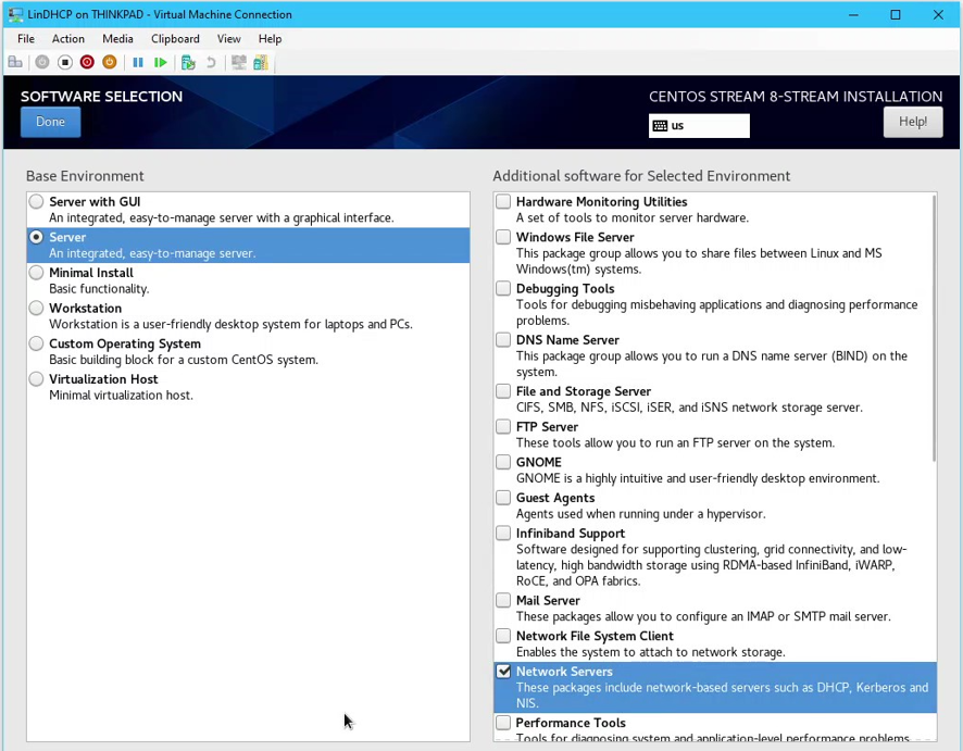
- Click Software Selection > Select Server as the base environment and Network Servers as additional software to be installed
- Click Network & Host Name
- Enter the Host Name as “LinDHCP”
- To setup the eth0 (LAN interface) in the bottom left corner of the screen click Configure...
- From the Editing LAN popup click on the tab IPv4 Settings
- Enter the following settings for the LAN network interface then click Save:
- Connection Name: “LAN”
- Method: Manual
- Address:
192.168.3.3
- Netmask:
28
- Gateway:
192.168.3.14
- DNS Servers:
192.168.3.1
- Search Domains:
cap.int
- Connect the ethernet by clicking the on/off toggle and view the summary of the configured settings > Click Done to return to the Installation Summary Page
- Click User Creation and create a administrator user named “_lsysadmin” with the password
Pa$$w0rd> Done
- Click Root Password and enter
Pa$$w0rd> Done
- Click Begin Installation
- When the installation is complete, click Reboot System
- Login to LinDHCP with
_lsysadminandPa$$w0rd
- View networking configuration with
ifconfig
- Test internet connectivity by entering
ping google.ca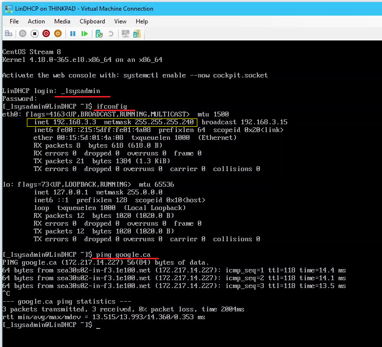
- ❗ Note: Pay attention to the prompt
$or#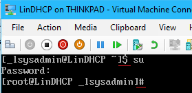
use suorsudo <command>
- Update the OS with
# dnf update(note that# yum update -yalso works)
- (Optional) Install traceroute with
# yum install traceroute -yand run$ traceroute google.ca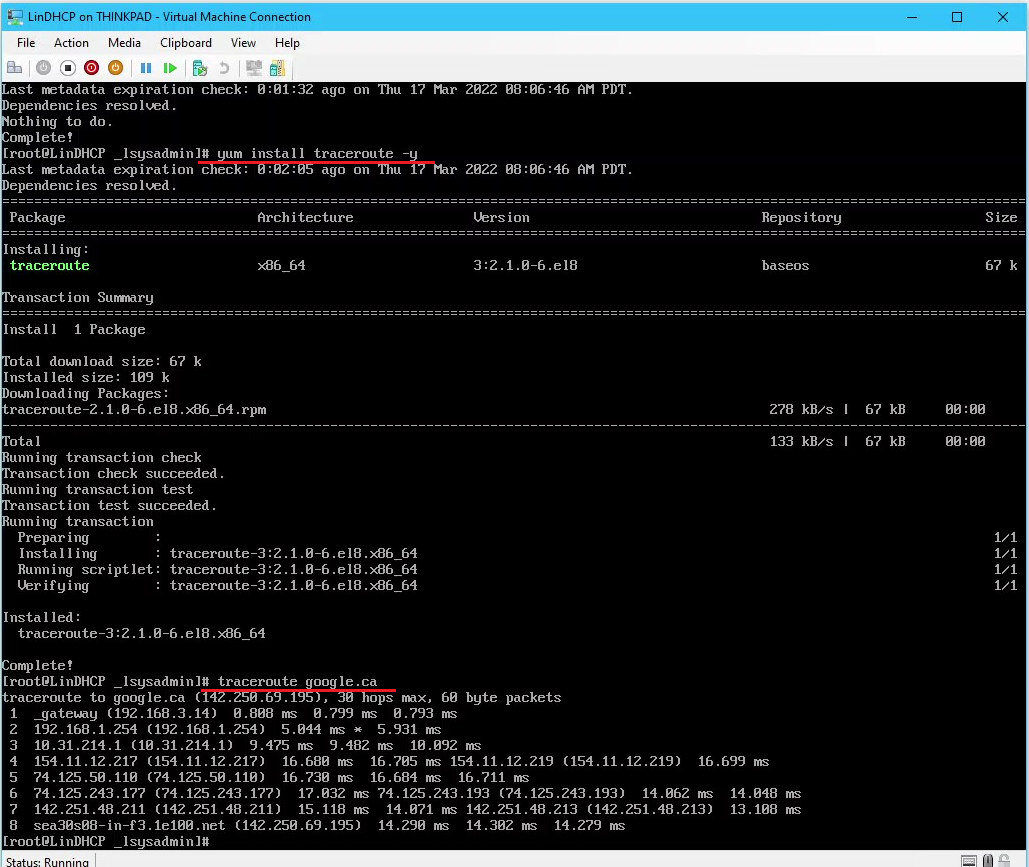
7.2 Install and Configure DHCP
7.2 Install and Configure DHCP
- Install the dhcp server package and dependencies with
# dnf install dhcp-server
- Open the dhcpd configuration file with
# nano /etc/dhcp/dhcpd.conf
- Write the following into dhcpd.conf
❗ Note: all entries need to be manually entered as copying into a Linux guest VM does not work, or create from a SSH session.
# set lease times
default-lease-time 600;
max-lease-time 7200;

# declare the DHCP Server
authoritative;

# Set Network address, subnet mask and gateway
subnet 192.168.3.0 netmask 255.255.255.248 {
	option routers 192.168.3.14;
	option broadcast-address 192.168.3.15;
	option subnet-mask 255.255.255.240;
	option domain-search "cap.int";
  option domain-name-servers 192.168.3.1;
	# IP address scope range - set only 1 which will be used for thinkpad
  range 192.168.3.13 192.168.3.13;
}

#Set DHCP Reservations for servers, find the MAC address in Hyper-V Settings
host DC1 {
	hardware ethernet 00:15:5D:05:4A:06;
	fixed-address 192.168.3.1;
}

host LinDHCP {
	hardware ethernet 00:15:5D:05:4A:08;
	fixed-address 192.168.3.3;
}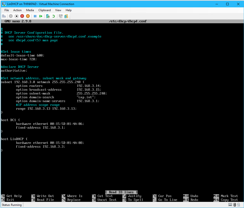
- When finished editing press CTRL+S then CTRL+X to save and exit
- Note: CTRL is shown as ^
- Start the service dhcpd, check the status to verify it is active, and set the service to start on reboot with:
# systemctl start dhcpd
# systemctl status dhcpd
# systemctl enable dhcpd.service
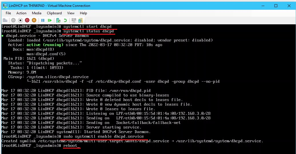
- Reboot the DHCP server and verify that the dhcpd service starts automatically with:
# reboot
# systemctl status dhcpd
7.3 Test DHCP on Thinkpad
7.3 Test DHCP on Thinkpad
- On Thinkpad set the LAN network adapter settings to Obtain an IP address automatically
- On Thinkpad open PowerShell as an administrator and run the following:
- ❗ If using RDP to access Thinkpad exit the session and work directly on the host. Reconnect after the settings are renewed.
ipconfig /release
ipconfig /renew
ipconfig /all
- View the DHCP Server IP for vEthernet LAN and notice it points to LinDHCP
- From LinDHCP view the DHCP leases with
$ cat /var/lib/dhcp/dhcpd.leases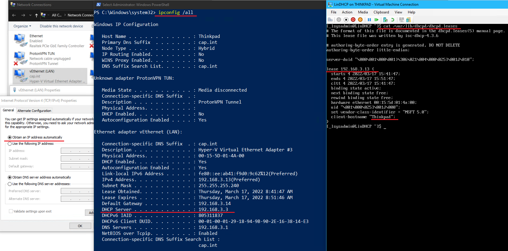
7.4 Join LinDHCP to cap.int Domain
7.4 Join LinDHCP to cap.int Domain
- Install the required packages on LinDHCP
# dnf install realmd sssd oddjob oddjob-mkhomedir adcli samba-common-tools krb5-workstation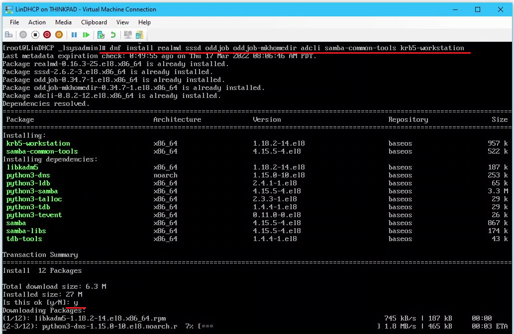
- Join the cap.int domain
- Use the Aidan admin credentials
# realm join --user=aidan cap.int
- View the computer object in ADUC
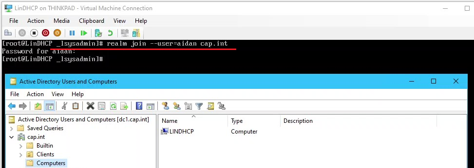
- Use the Aidan admin credentials
- Move the computer object LINDHCP into the OU=DHCP
- On LinDHCP login with the domain admin
aidan@cap.int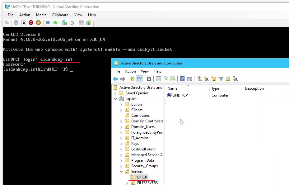
- In DNS Manager on Thinkpad add a A record for LinDHCP
- ⏲ Checkpoint LinDHCP and name it “Functional DHCP - future reservations need to be added”
- Shut down the VM and set the memory to 512 MB static
8.0 iSCSI SAN
Create a SAN virtual machine which will not join the domain as it is mimicking physical hardware. It does need to be added to Server Manager for a to have a GUI. This iSCSI target will have RAID 6 to allow for 2 disk failure and a ReFS file system on the 2 volumes. The main iSCSI virtual disk will be 100GB as it will contain the VHDX for FILE1, FILE2, DC2 as well as the file share data. The second vDisk will be used as the quorum witness.
8.1 Create the SAN VM with Server Core
8.1 Create the SAN VM with Server Core
- ⏲ Checkpoint DC1 and name it “Before SAN”
- In Hyper-V on Thinkpad, create a new VM named “SAN” with using the script from Appendix E to create the following:
- Memory: 2048 MB Static (will be set to 512 MB after)
- Network: LAN
- Hard Disk: Differencing disk to ParentServer2019-Core.vhdx
- Operating System: Windows Server 2019 (Core)
- Connect and start the SAN virtual machine
- Set the admin password to
Pa$$w0rd
- Set LAN networking in
sconfig- IP Address:
192.168.3.4
- Subnet:
255.255.255.240(/28)
- Default Gateway:
192.168.3.14
- DNS:
192.168.3.1&8.8.8.8
- IP Address:
- From PowerShell run the following:
Get-NetAdapter
Rename-NetAdapter -Name "Ethernet" -NewName "LAN"

Get-LocalUser
Rename-LocalUser -Name "Administrator" -NewName "_lsysadmin"

Restart-Computer -Force
- From
sconfigselect option2to rename the computer to “SAN”
- Verify all post-install tasks are complete and are configured correctly as per Appendix G
- Restart the VM with
Restart-Computer -Force
8.2 Add a Non-Domain Member to Server Manager
8.2 Add a Non-Domain Member to Server Manager
- On Thinkpad open PowerShell and run the following commands:
# Update hosts file to map SAN's IP to name "SAN"
Add-Content -Path C:\Windows\System32\drivers\etc\hosts -Value "192.168.3.4 SAN"

#Start the WinRM service
Start-Service -Name WinRM

#Set SAN host as trusted
Set-Item -Path WSMan:\localhost\Client\TrustedHosts -Value SAN -Concatenate -Force

#View the list
Get-ChildItem -Path WSMan:\localhost\Client\TrustedHosts | Format-List
- Open Server Manager and add SAN from the DNS tab
- To fix the Kerberos authentication error, right-click SAN > Manage As > Enter the following credentials
- User:
san\_lsysadmdin- as SAN is a workgroup computer not a cap.int domain member, the domain value issan\for the VM’s name
- Password:
Pa$$w0rd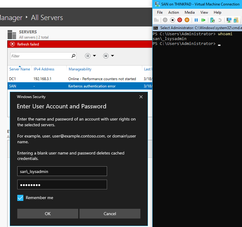
Use the local admin account as SAN is not a cap.int domain member 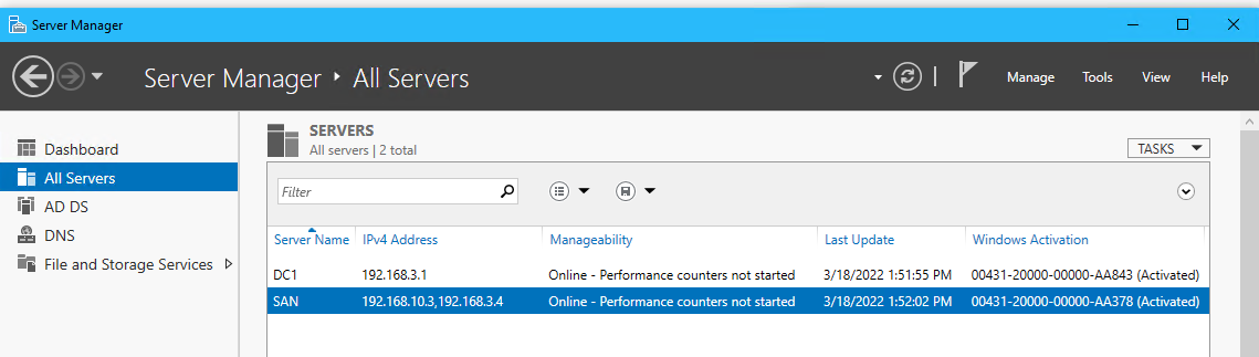
- User:
8.3 Setup the iSCSI SAN RAID 6 Hardware
8.3 Setup the iSCSI SAN RAID 6 Hardware
- From Thinkpad on PowerShell create eight 25GB disks and attach to the SAN VM with the following:
- ❗ This may take some time as the disk size is fixed
New-VHD -Path V:\VMs\VHDX\Disk1.vhdx -Fixed -SizeBytes 25GB
Add-VMHardDiskDrive -VMName SAN -Path V:\VMs\VHDX\Disk1.vhdx

New-VHD -Path V:\VMs\VHDX\Disk2.vhdx -Fixed -SizeBytes 25GB
Add-VMHardDiskDrive -VMName SAN -Path V:\VMs\VHDX\Disk2.vhdx

New-VHD -Path V:\VMs\VHDX\Disk3.vhdx -Fixed -SizeBytes 25GB
Add-VMHardDiskDrive -VMName SAN -Path V:\VMs\VHDX\Disk3.vhdx

New-VHD -Path V:\VMs\VHDX\Disk4.vhdx -Fixed -SizeBytes 25GB
Add-VMHardDiskDrive -VMName SAN -Path V:\VMs\VHDX\Disk4.vhdx

New-VHD -Path V:\VMs\VHDX\Disk5.vhdx -Fixed -SizeBytes 25GB
Add-VMHardDiskDrive -VMName SAN -Path V:\VMs\VHDX\Disk5.vhdx

New-VHD -Path V:\VMs\VHDX\Disk6.vhdx -Fixed -SizeBytes 25GB
Add-VMHardDiskDrive -VMName SAN -Path V:\VMs\VHDX\Disk6.vhdx

New-VHD -Path V:\VMs\VHDX\Disk7.vhdx -Fixed -SizeBytes 25GB
Add-VMHardDiskDrive -VMName SAN -Path V:\VMs\VHDX\Disk7.vhdx

New-VHD -Path V:\VMs\VHDX\Disk8.vhdx -Fixed -SizeBytes 25GB
Add-VMHardDiskDrive -VMName SAN -Path V:\VMs\VHDX\Disk8.vhdx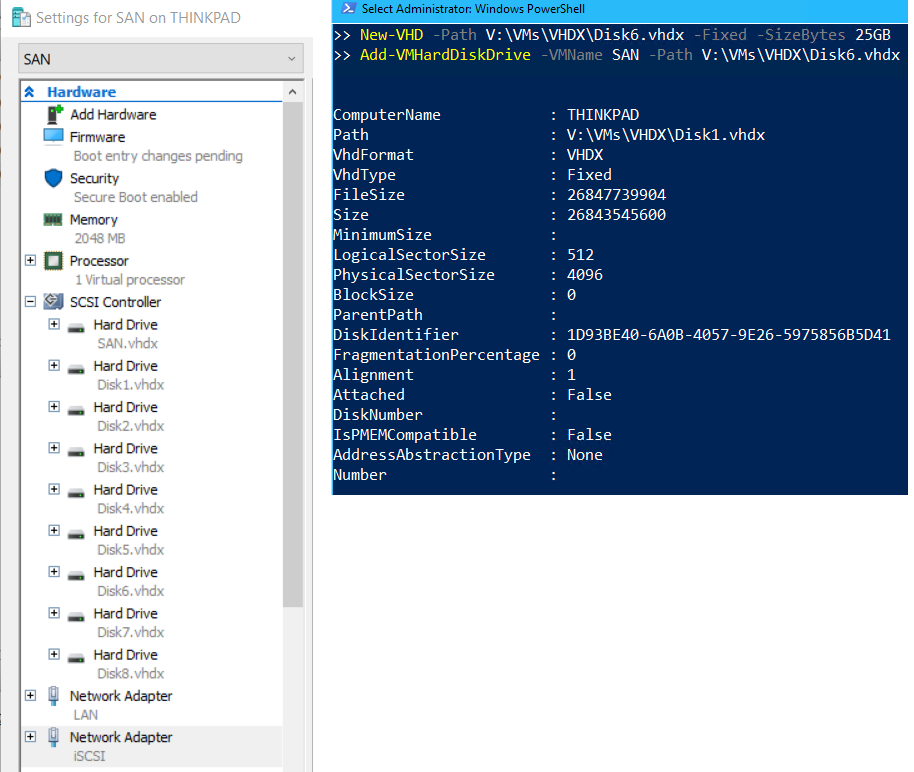
❗ Because SAN has so many disks, do NOT checkpoint this VM, this will also apply to the nested servers HV1, and HV2
- In SAN’s settings in Hyper-V, add a Network Adapter and connect it to the iSCSI virtual switch
- On SAN go to
sconfig> Option8> set the Network Adapter Settings to the following:- IP Address:
192.168.10.3(Static)
- Subnet Mask:
255.255.255.248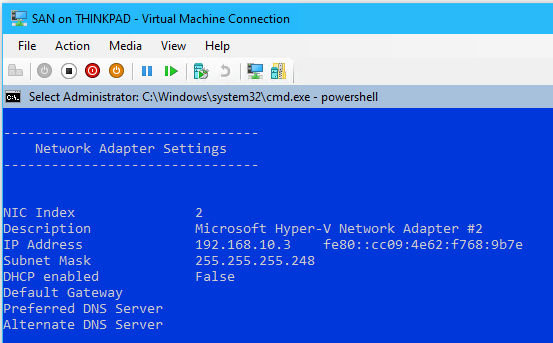
- IP Address:
- From PowerShell in SAN rename the new network adapter to “iSCSI”
Get-NetAdapter
Rename-NetAdapter -Name "Ethernet" -NewName "iSCSI"

#View Changes
Get-NetAdapter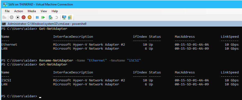
- Enable jumbo packets with the size 9014 bytes by entering the following in PS:
# View settings before
Get-NetAdapterAdvancedProperty -Name "iSCSI"

# Enable jumbo frames and set size
Set-NetAdapterAdvancedProperty -Name "iSCSI" -RegistryKeyword "*JumboPacket" -Registryvalue 9014

# View changes
Get-NetAdapterAdvancedProperty -Name "iSCSI"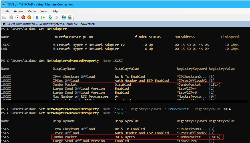
8.4 Configure SAN’s Storage Pool, Virtual Disks, and Volumes
8.4 Configure SAN’s Storage Pool, Virtual Disks, and Volumes
- From Server Manager > go to File and Storage Services > Volumes > Storage Pools
- Under the Storage Pools section > Windows Storage > Right click Primordial > New Storage Pool... to open the Wizard
- Complete the New Storage Pool Wizard with the following:
- Pool Name: “Pool1”
- Physical Disks: Select all 6 and set the allocation to Automatic
- Confirm & click Create
- Create a virtual disk named “vDisk” from PowerShell on SAN with the following
❗ Windows Server 2019 has a known bug where vDisks can not be made from Server Manager which is why
PowerShellis used instead# Create a RAID 6 virtual disk by setting resiliency=parity & physical disk redundancy=2 New-VirtualDisk ` -StoragePoolFriendlyName "Pool1" ` -FriendlyName "vDisk" ` -Size 100GB ` -ProvisioningType Fixed ` -ResiliencySettingName "Parity" ` -PhysicalDiskRedundancy 2
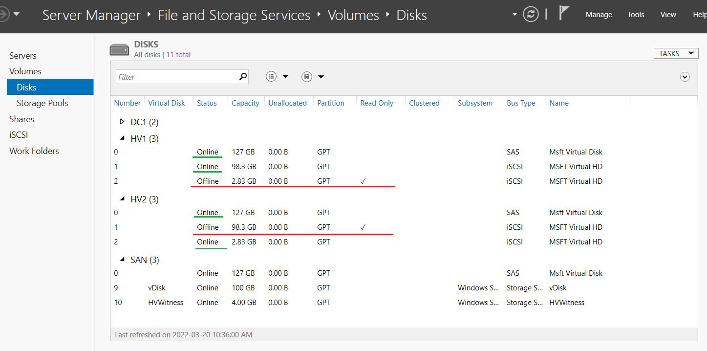
- From Server Manager on Thinkpad > go to Volumes > Disks
- Expand SAN (2) right click vDisk > click Bring Online
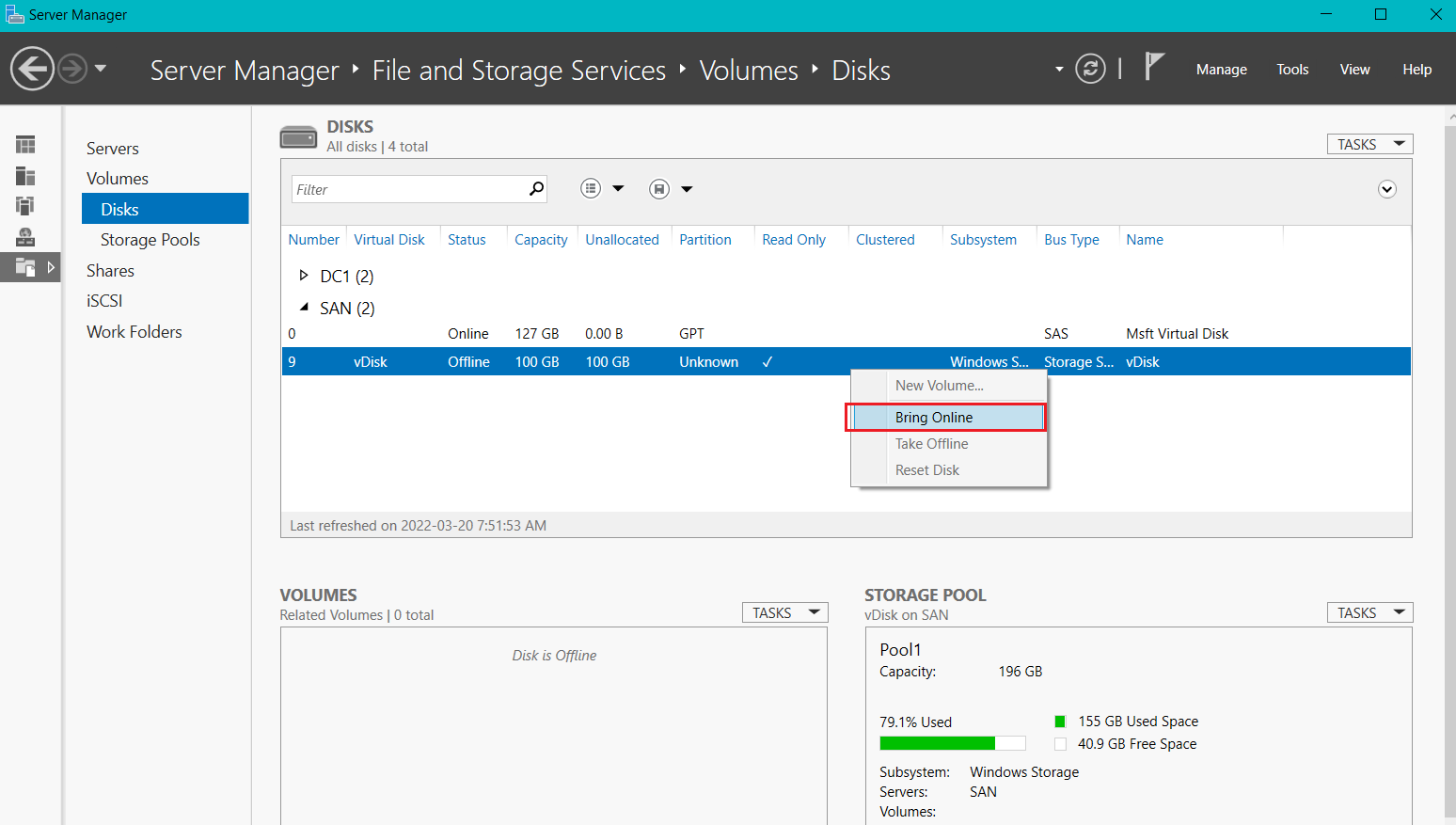
- Right-click vDisk again > select Initialize
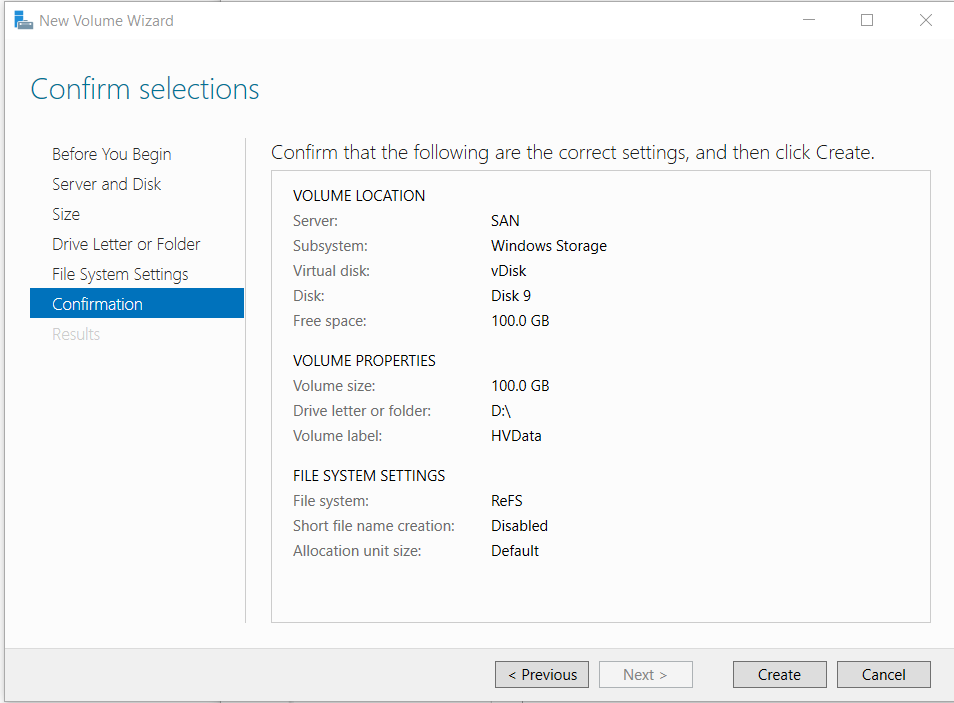
- In the section Volumes click the link To create a volume, start the New Volume Wizard
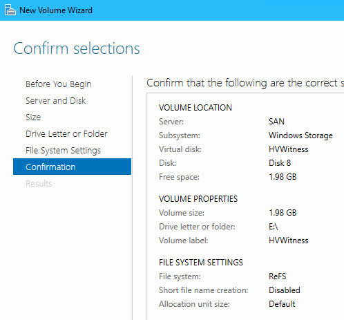
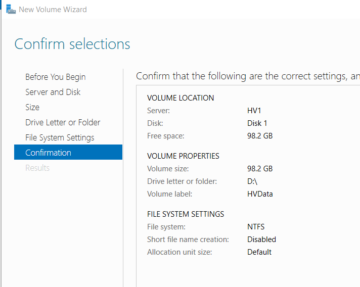
- Complete the New Volume Wizard with the following:
- Server and Disk: Select SAN and Disk 9
- Size: 100 GB (the maximum available capacity)
- Drive Letter or folder: Assign to drive letter D
- File System Settings: File system set to ReFS and label the volume “HVData”
8.5 Add the iSCSI Target Role on SAN
8.5 Add the iSCSI Target Role on SAN
- In Server Manager click All Servers in the left panel
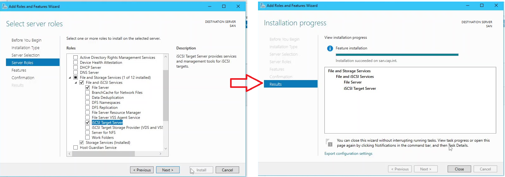
- Right click server SAN > click Add Roles and Features
- Install the iSCSI Target Server role >Accept recommended addons which includes the File Server role
8.6 Create an iSCSI Virtual Disk
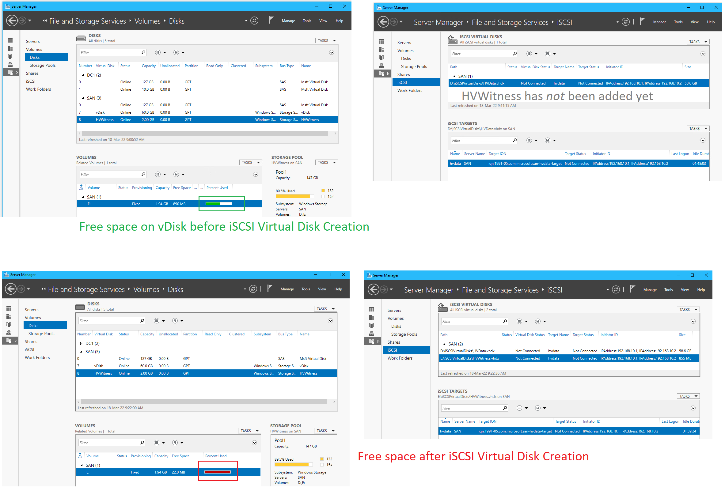
8.6 Create an iSCSI Virtual Disk
- Open Server Manager navigate to File and Storage Spaces > iSCSI
- Click the link To create an iSCSI virtual disk, start the New iSCSI Virtual Wizard
- Complete the iSCSI Virtual Disk Wizard with the following
- Name: “HVData”
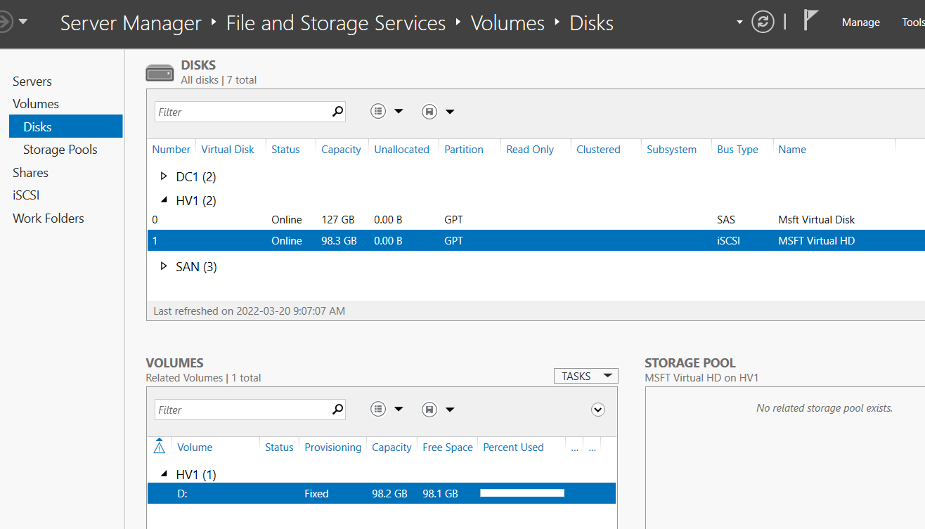
- Disk Size: 98.3 GB (the maximum)
- iSCSI Target: Create new target named “HVData” and add IP addresses that will be used for the nested Hyper-V servers to be the initiators
192.168.10.1and192.168.10.2for HV1 and HV2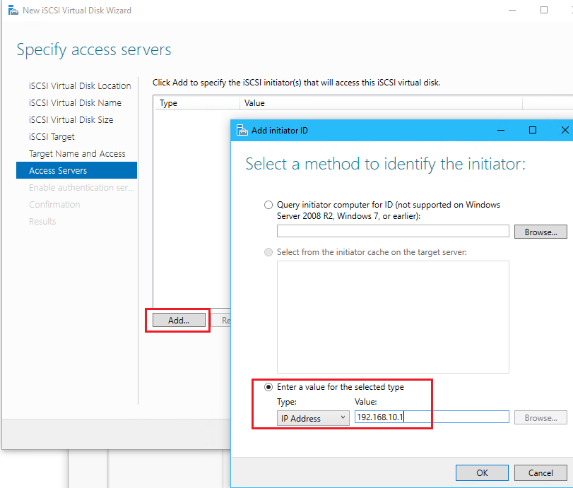
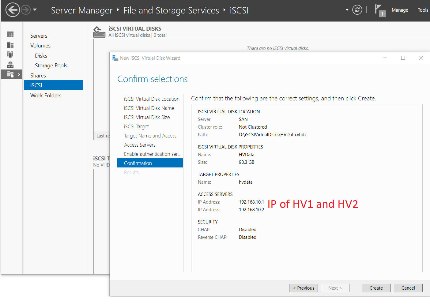
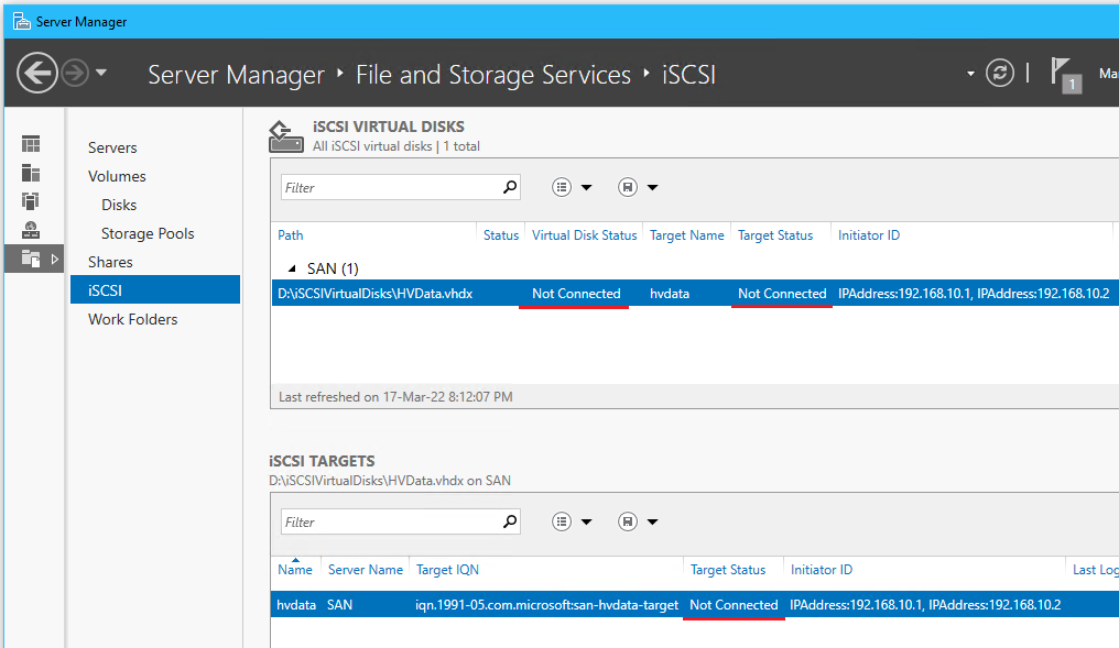
- Notice that the target and virtual disk status is Not Connected this will be setup later
8.7 Create a 2GB vDisk for the Quorum Witness
8.7 Create a 2GB vDisk for the Quorum Witness
- From Server Manager go to File and Storage Services > Volumes > Storage Pools
- On SAN run create a virtual disk from the free 22 GB in Pool1 with the following PS script:
# Create a RAID 6 virtual disk by setting resiliency=parity & physical disk redundancy=2
New-VirtualDisk `
-StoragePoolFriendlyName "Pool1" `
-FriendlyName "HVWitness" `
-Size 2GB `
-ProvisioningType Fixed `
-ResiliencySettingName "Parity" `
-PhysicalDiskRedundancy 2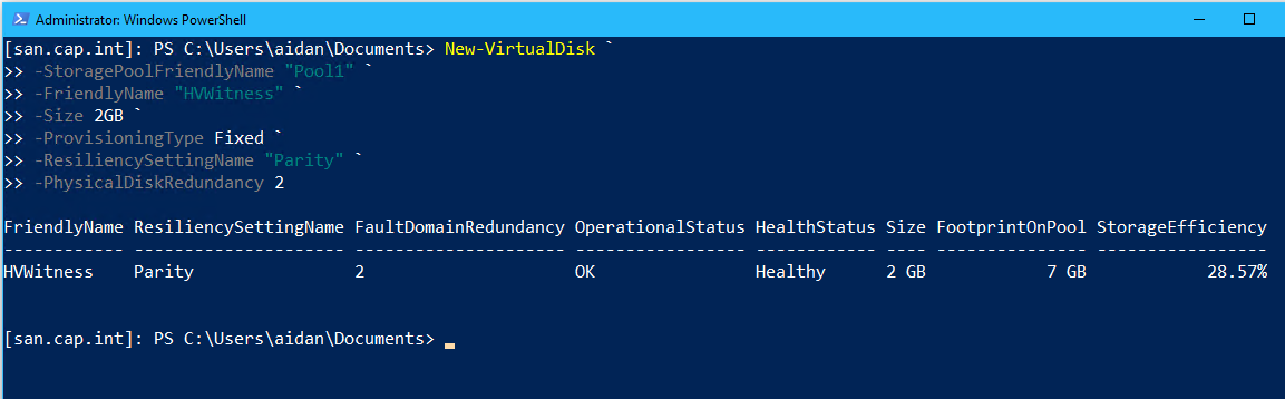
Access a PS session on SAN from Server Manager on Thinkpad (or connect to the VM directly) 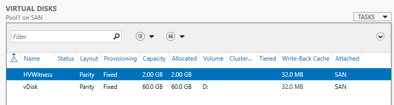
- From Volume > Disks, bring HVData online, initialize, create volume
- Go to the iSCSI tab > click TASKS for iSCSI Virtual Disks > Click New iSCSI Virtual Disk
- Complete the iSCSI Virtual Wizard and add HVWitness
- Notice that the existing iSCSI target already exists from the last disk
- ❗Notice the change of free space on the virtual disk before and after the iSCSI virtual disk has been made - this is expected
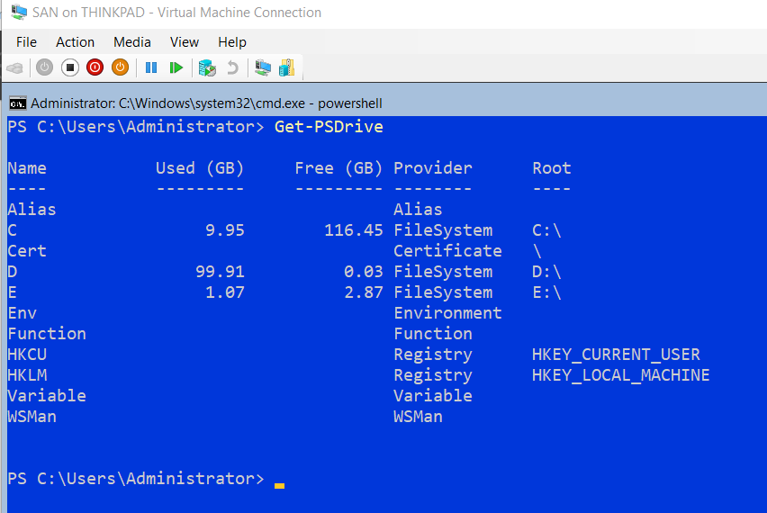
- (Optional) On SAN enter
Get-PSDrivein PowerShell to see the volumes- D:\→ HV Data
- E:\→ HVWitness
- Shut down the SAN virtual machine
- Set the memory to 512 MB Static
9.0 Configure 2 Nested Hyper-V Failover Cluster Servers
Create 2 nested Hyper-V servers which will contain FILE1, FILE2, and DC2 VMs. Each Hyper-V machine needs an external switch for LAN and HB with the network adapters set to enable MAC spoofing. The nested Hyper-V machines will connect to the iSCSI SAN and the disk will be a cluster shared disk (CSV) to allow both VMs access at the same time. Both HV’s will be clustered together to allow for resiliency and live migration of VM’s.
9.1 Create the Hyper-V VM & Complete Post-Install Tasks
9.1 Create the Hyper-V VM & Complete Post-Install Tasks
- Create a VM named “HV1” with 4GB of RAM using the script from Appendix E
- Start the virtual machine HV1 and set the administrator password to
PaSSw0rd
- Enter
powershelland run the post installation tasks script below: (See Appendix F for future VMs)- $IP =
192.168.3.5
- $SrvName =
HV1
- $SrvOUPath =
OU=HYPERV,OU=Servers,DC=cap,DC=int
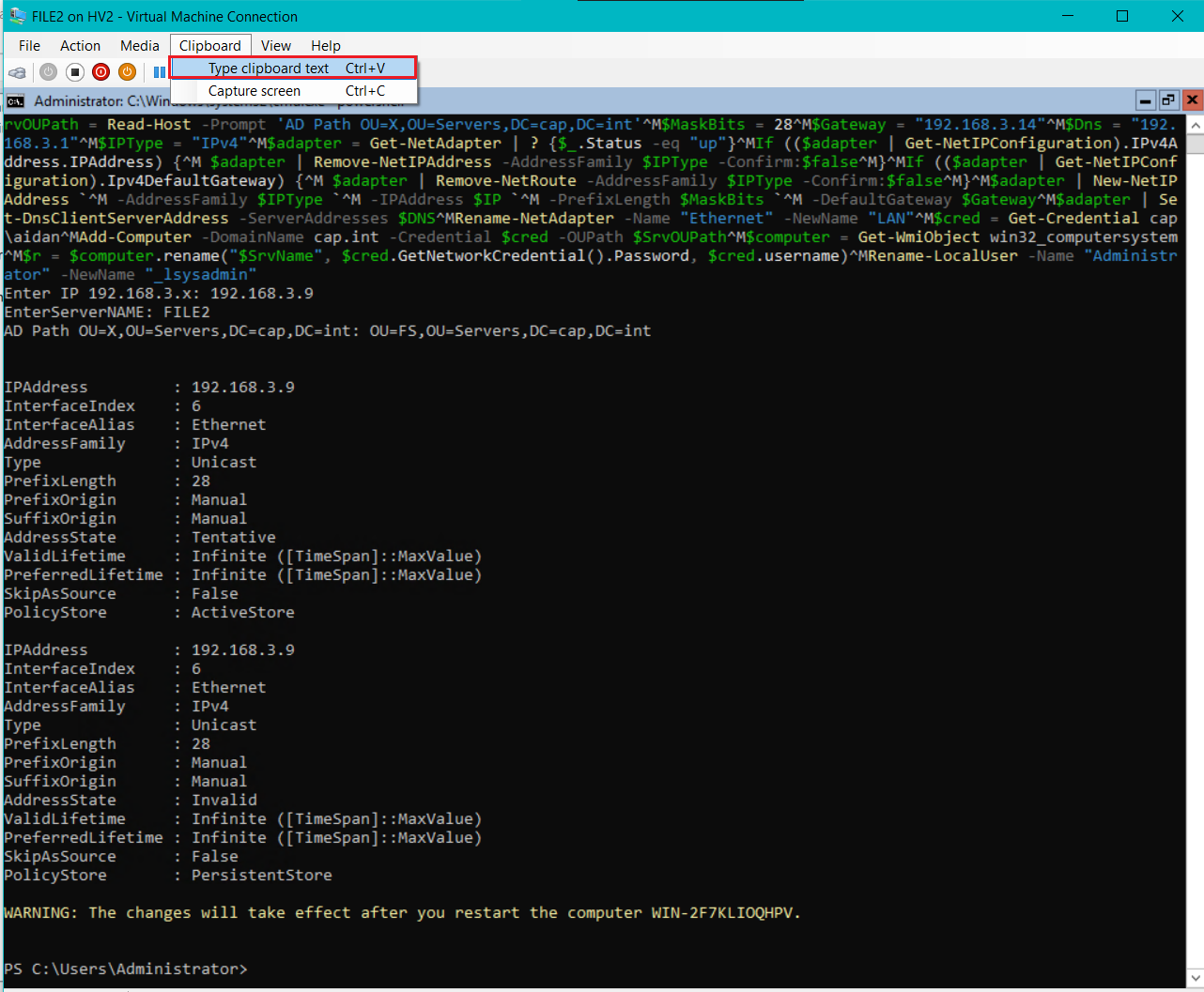
#
# Post-installation tasks
#
$IP = Read-Host -Prompt 'Enter IP 192.168.3.x'
$SrvName = Read-Host -Prompt 'EnterServerNAME'
$SrvOUPath = Read-Host -Prompt 'AD Path OU=X,OU=Servers,DC=cap,DC=int'
$MaskBits = 28
$Gateway = "192.168.3.14"
$Dns = "192.168.3.1"
$IPType = "IPv4"


# Retrieve the network adapter that you want to configure
$adapter = Get-NetAdapter | ? {$_.Status -eq "up"}
# Remove any existing IP, gateway from our ipv4 adapter
If (($adapter | Get-NetIPConfiguration).IPv4Address.IPAddress) {
 $adapter | Remove-NetIPAddress -AddressFamily $IPType -Confirm:$false
}
If (($adapter | Get-NetIPConfiguration).Ipv4DefaultGateway) {
 $adapter | Remove-NetRoute -AddressFamily $IPType -Confirm:$false
}
 # Configure the IP address and default gateway
$adapter | New-NetIPAddress `
 -AddressFamily $IPType `
 -IPAddress $IP `
 -PrefixLength $MaskBits `
 -DefaultGateway $Gateway
# Configure the DNS client server IP addresses
$adapter | Set-DnsClientServerAddress -ServerAddresses $DNS
# Rename the Network Adapter
Rename-NetAdapter -Name "Ethernet" -NewName "LAN"

# Name Computer, add to Domain and OU placement
$cred = Get-Credential cap\aidan
Add-Computer -DomainName cap.int -Credential $cred -OUPath $SrvOUPath
$computer = Get-WmiObject win32_computersystem
$r = $computer.rename("$SrvName", $cred.GetNetworkCredential().Password, $cred.username)

#Rename the local admin account
Rename-LocalUser -Name "Administrator" -NewName "_lsysadmin"

# Restart-Computer -Force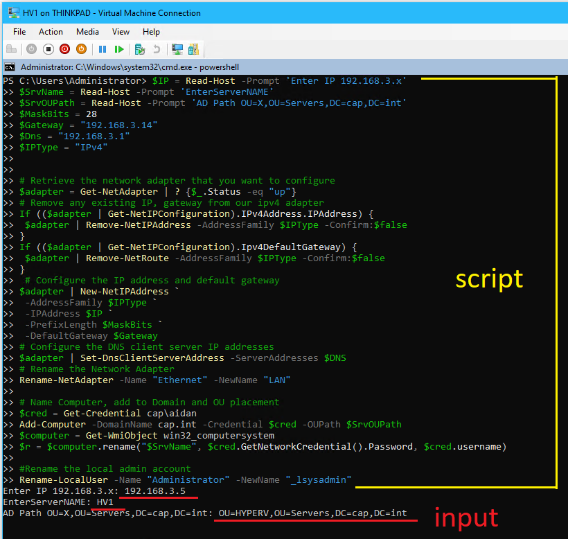
- $IP =
- When complete enter
Restart-Computer -Force
- Login to the SAN virtual machine as cap\aidan
- Complete the following post-install tasks in
powershell(see Appendix G for future reference)whoami: verify server is a domain member and that the admin aidan@cap.int is logged in
tracert google.ca: verify internet connectivity and DNS
ping LinDHCP: test DNS to a domain server
ipconfig: verify IPv4 address, subnet, default gateway
Get-LocalUser: verify the local admin account has been renamed to _lsysadmin
Get-NetAdapter: verify the network adapter has been renamed
- Complete the following post-install tasks in
sconfig(see Appendix G for future reference)11Windows Activation, verify Windows is activated and has the 180 day trial
6Download and Install updates
- Complete the following post-install tasks from Server Manager (see Appendix G for future reference)
- Open DNS Manager and view the host A record
- Open ADUC and verify the computer object is in the correct OU
- Complete the following post-install tasks from Thinkpad (see Appendix G for future reference)
- Add the HV1 VM to Server Manager and manage as
cap\aidan
- ⏲ Checkpoint (if needed, but try to keep to a minimum)
- Add the HV1 VM to Server Manager and manage as
10. Repeat all steps to make the 2nd server HV2
9.2 Complete Nested Hypervisor Hardware and Network Requirements
9.2 Complete Nested Hypervisor Hardware and Network Requirements
- On Thinkpad’s Hyper-V manager, open the settings for HV1
- Under Hardware > Processor > Set to 2 Virtual Processors
- Under Hardware > Network Adapter LAN > Advanced Features > Check Enable MAC address spoofing
- Add Network Adapter’s to the iSCSI, HB, and LM switches
- Start HV1 and enter
sconfig>8view network settings & view the MAC addresses of each adapter in Hyper-V Manager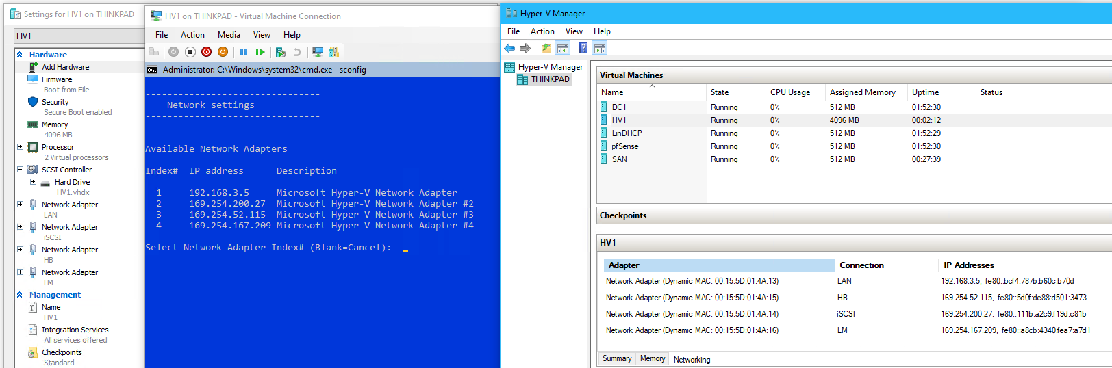
The order the net adapter is added in HV1 settings > the index #.
- From
sconfigset the network adapters with the following:Index# - Network IP Address Subnet 1 - LAN 192.168.3.5 255.255.255.240 2 - iSCSI 192.168.10.1 255.255.255.248 3 - HB 192.168.20.1 255.255.255.248 4 - LM 192.168.30.1 255.255.255.252 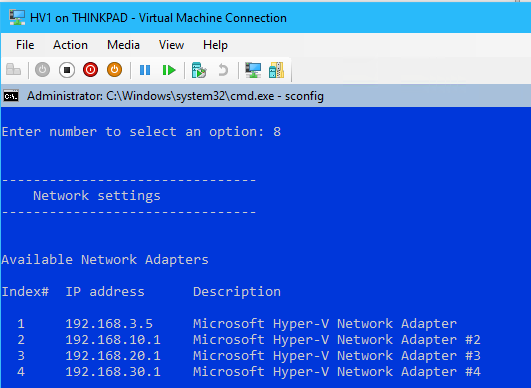
- From PowerShell rename the network adapters
❗ Match the Ethernet to the MAC address each time before running!
Get-NetAdapter | Sort-Object -Property "InterfaceDescription"

Rename-NetAdapter -Name "Ethernet" -NewName "iSCSI"
Rename-NetAdapter -Name "Ethernet 2" -NewName "HB"
Rename-NetAdapter -Name "Ethernet 3" -NewName "LM"
#View
Get-NetAdapter | Sort-Object -Property "InterfaceDescription"
- Restart the server to apply the renaming changes with
Restart-Computer -Force
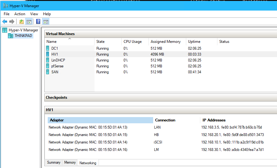
- Verify that the proper IP address is assigned to the network adapter (compare to MAC address) and that the net adapter is renamed with
ipconfig /all, Hyper-V Manager, and/or with the following code:#View Get-NetAdapter | Sort-Object -Property "ifIndex" -Descending |Format-Table -Property "ifIndex", "Name", "MacAddress" Get-NetIPAddress -AddressFamily IPv4 | Sort-Object -Property "ifIndex" -Descending | Format-Table -Property "ifIndex", "IPAddress", "PrefixLength" Get-NetIPConfiguration | Sort-Object -Property "InterfaceIndex" -Descending | Format-Table -Property "InterfaceIndex", "InterfaceAlias", "IPv4Address"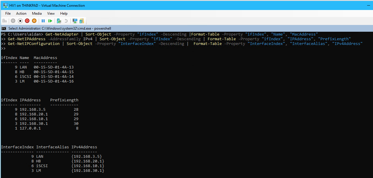
- Enable jumbo frames on the network adapter connected to iSCSI with the following:
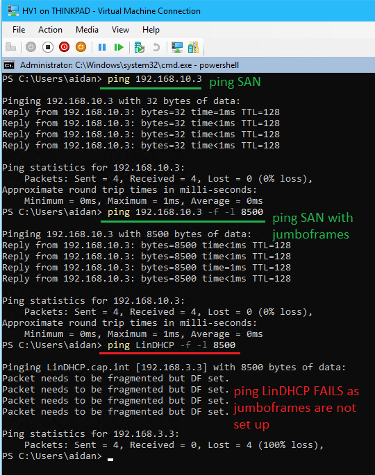
# View settings before
Get-NetAdapterAdvancedProperty -Name "iSCSI"
# Enable jumbo frames and set size
Set-NetAdapterAdvancedProperty -Name "iSCSI" -RegistryKeyword "*JumboPacket" -Registryvalue 9014
# View changes
Get-NetAdapterAdvancedProperty -Name "iSCSI"

# Test sending jumbo frames (after the VM's have been made and also have jumbo frames enabled)
ping 192.168.10.3 -f -l 8500
- From HV1 send a ping with jumbo frames to SAN
ping 192.168.10.3 -f -l 8500- ❗ No DNS settings are set for this network requiring IP addresses
-fSpecifies that echo Request messages are sent with the Do not Fragment flag in the IP header set to 1 (available on IPv4 only). The echo Request message can't be fragmented by routers in the path to the destination. This parameter is useful for troubleshooting path Maximum Transmission Unit (PMTU) problems.
/l <size>Specifies the length, in bytes, of the Data field in the echo Request messages. The default is 32. The maximum size is 65,527.
- Open the firewall so the server allows ICMP pings
#Allow Ping
netsh advfirewall firewall add rule name="ICMP Ping Allow" protocol="icmpv4:8,any" dir=in action=allow

#Block ping (for referenc)
netsh advfirewall firewall add rule name="ICMP Ping Block" protocol="icmpv4:8,any" dir=in action=block
- Shutdown the HV1 VM
- Enable nested virtualization for the virtual machine by running the following from PowerShell on the host Thinkpad:
#Run from Thinkpad Host while the guest VM is off
Get-VMProcessor -VMName HV1 | fl
Set-VMProcessor -VMName HV1 -ExposeVirtualizationExtensions $true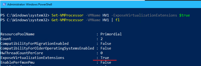
- Repeat steps 1-14 for HV2
Index# - Network IP Address Subnet 1 - LAN 192.168.3.6 255.255.255.240 2 - iSCSI 192.168.10.2 255.255.255.248 3 - HB 192.168.20.2 255.255.255.248 4 - LM 192.168.30.2 255.255.255.252
9.3 Connect HV1 to the iSCSI Target
9.3 Connect HV1 to the iSCSI Target
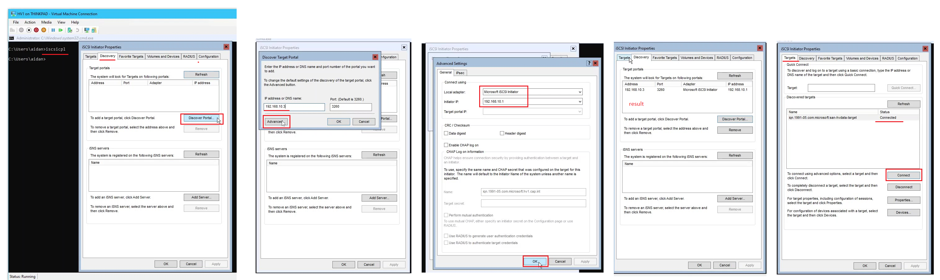
- From HV1 enter
iscsicplto open the iSCSI Initiator
- In the iSCSI Initiator Properties popup, click the Discovery tab
- Click Discover Portal and enter in SAN’s IP
192.168.10.3and click Advanced...
- Set Local adapter: to Microsoft iSCSI Initiator
- Set Initiator IP: 192.168.10.1 the IP of HV1
- Click OK at the bottom of the window
- Click Discover Portal and enter in SAN’s IP
- Click on the Targets tab > click Connect
- If the connection fails, restart the Storage Server (SAN) or restart the iSCSI Target Service.
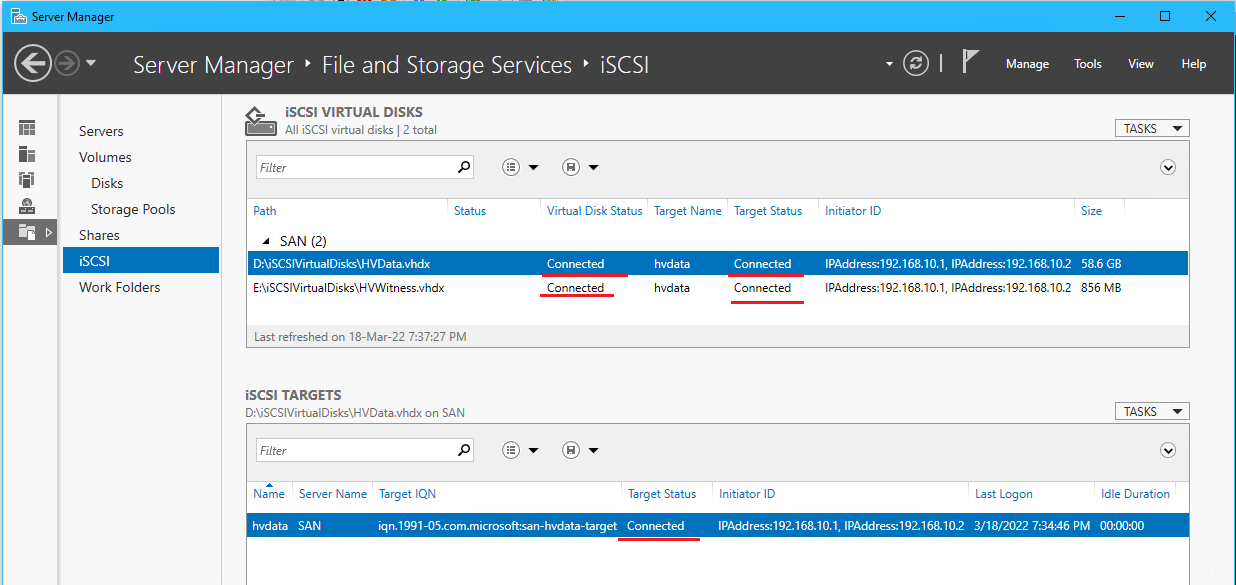
- Go to Volumes > Disks > and expand HV1
- Right click iSCSI disk > bring online, initialize, and create a volume with NTFS named “HVData”
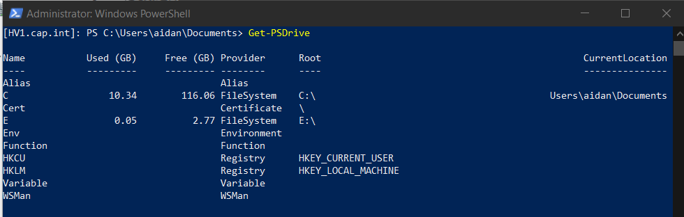
View the drives on HV1 with the PS command Get-PSDrive
- Enable File Sharing by running the following command on HV1’s PowerShell:
Set-NetFirewallRule -DisplayGroup "File And Printer Sharing" -Enabled True -Profile Any
- Make the directories VMs\VHDX on the iSCSI virtual disk from file explorer
\\192.168.3.5\d$or PowerShellmkdir VMs\VHDX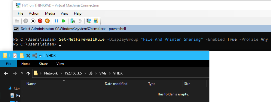
8. Repeat steps 1-3 & 6 on HV2 for the iSCSI initiator. The drive does not need to be formatted again and note that only 1 VM can be connected at a time
9.4 Add the Hyper-V Role
9.4 Add the Hyper-V Role
- ‼ Login to account cap\aidan on Thinkpad and complete the rest of the project from here. Multiple issues are caused from working from the thinkpad\aidan account in future steps
- ⏲ Checkpoint DC1 and name it “Before Nested HV”
- From Server Manager right-click HV1 > select Add Roles and Features
- Complete the Add Roles and Features Wizard and install the role Hyper-V with the following:
- Server Roles: Select Hyper-V
- Features: ❗ Select Failover Clustering or install separately after
- Virtual Switches: Leave all unchecked as switches will be made manually later
- Migration: Leave unchecked
- Default Stores: Default VHDX file location =
D:\VMs\VHDX, VM configuration files =D:\VMs
- Confirmation: Check Restart the destination server automatically if required
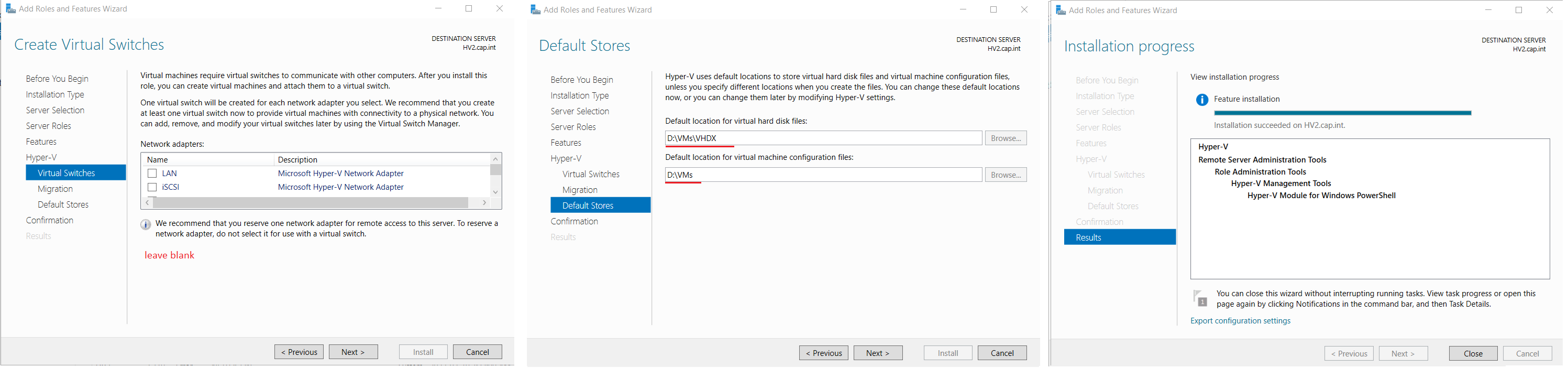
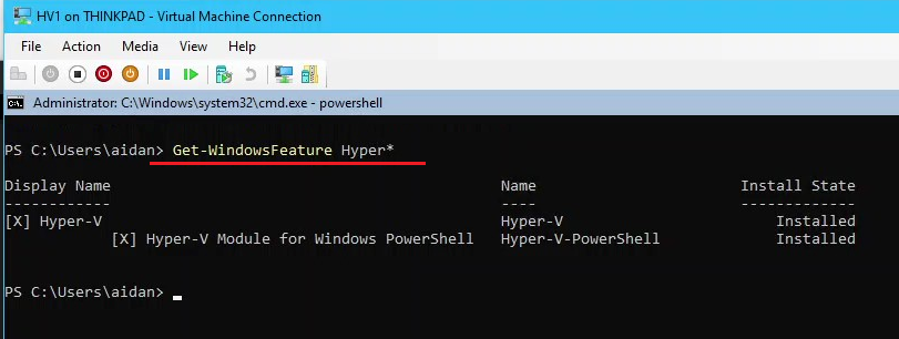
- Verify the role installation by running the following PS command on HV1
Get-WindowsFeature Hyper*
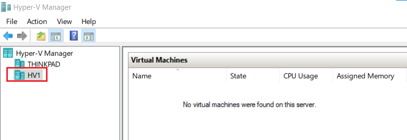
- From Hyper-V Manager on Thinkpad, right click Hyper-V Manager > Connect to Server > Browse and select HV1
- Click HV1 in Hyper-V Manager > Virtual Switch Manager
- Create a new virtual network switch named “LANext” and connect it to External network: Microsoft Hyper-V Network Adapter
9.5 Configure Hyper-V Failover Clustering
9.5 Configure Hyper-V Failover Clustering
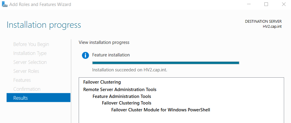
- From Server Manager install the feature Failover Clustering to HV1 & HV2
- In Server Manager go to the Tools drop down and select Failover Cluster Manager
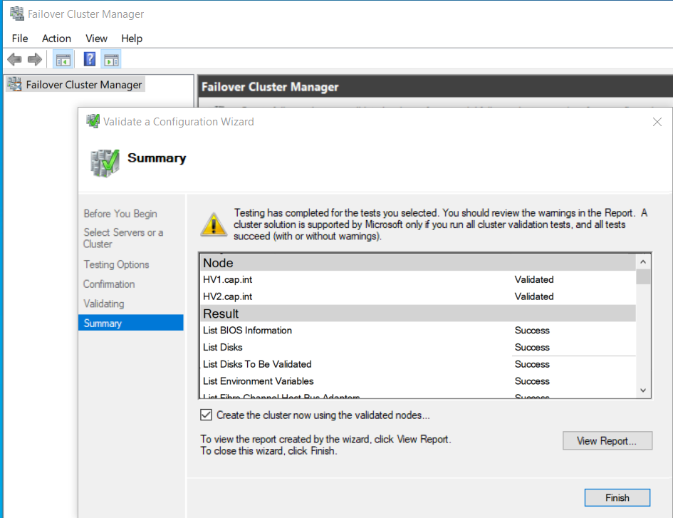
- Right-click Failover Cluster Manager > Select Validate Configuration
- Complete the Validate a Configuration Wizard with the following:
- Select Servers:
HV1.cap.intandHV2.cap.int
- Testing Options: Select Run all tests
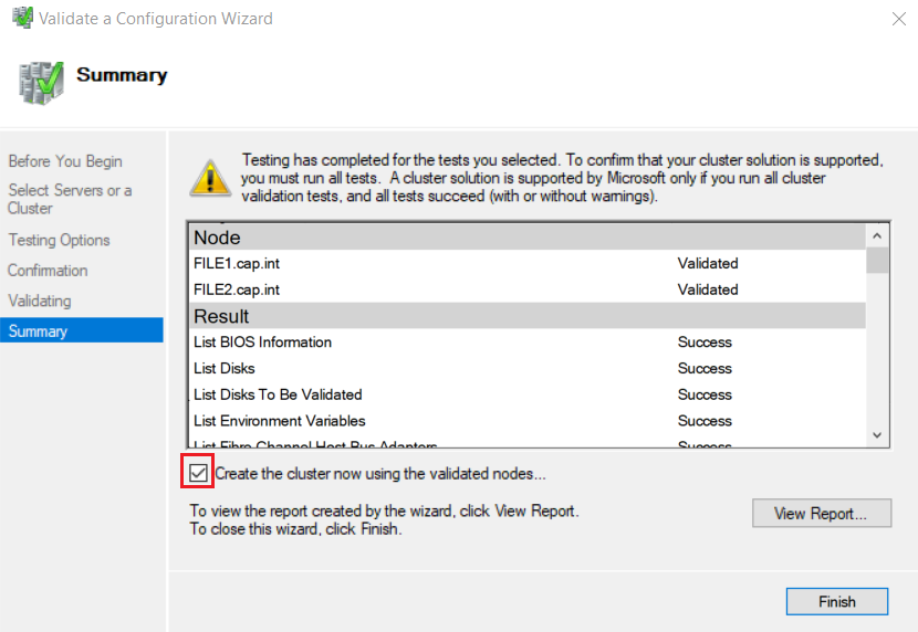
- Summary: View results and any errors. Check Create the cluster now using the validated nodes
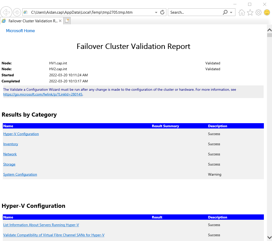
- Select Servers:
- Complete the Create Cluster Wizard with the following:
- Access Point for Administering the Cluster: Name =
HV-Cluser, Address =192.168.3.7
- Confirmation: Uncheck Add all eligible storage to the cluster
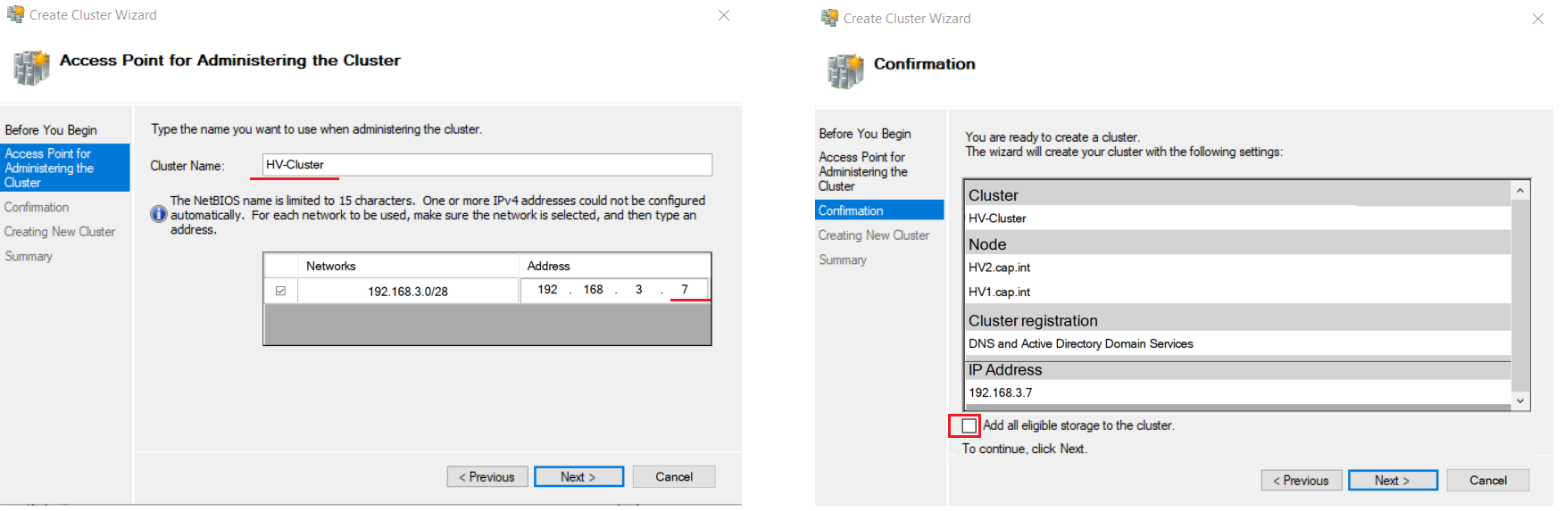
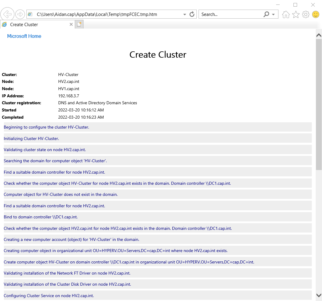
- Access Point for Administering the Cluster: Name =
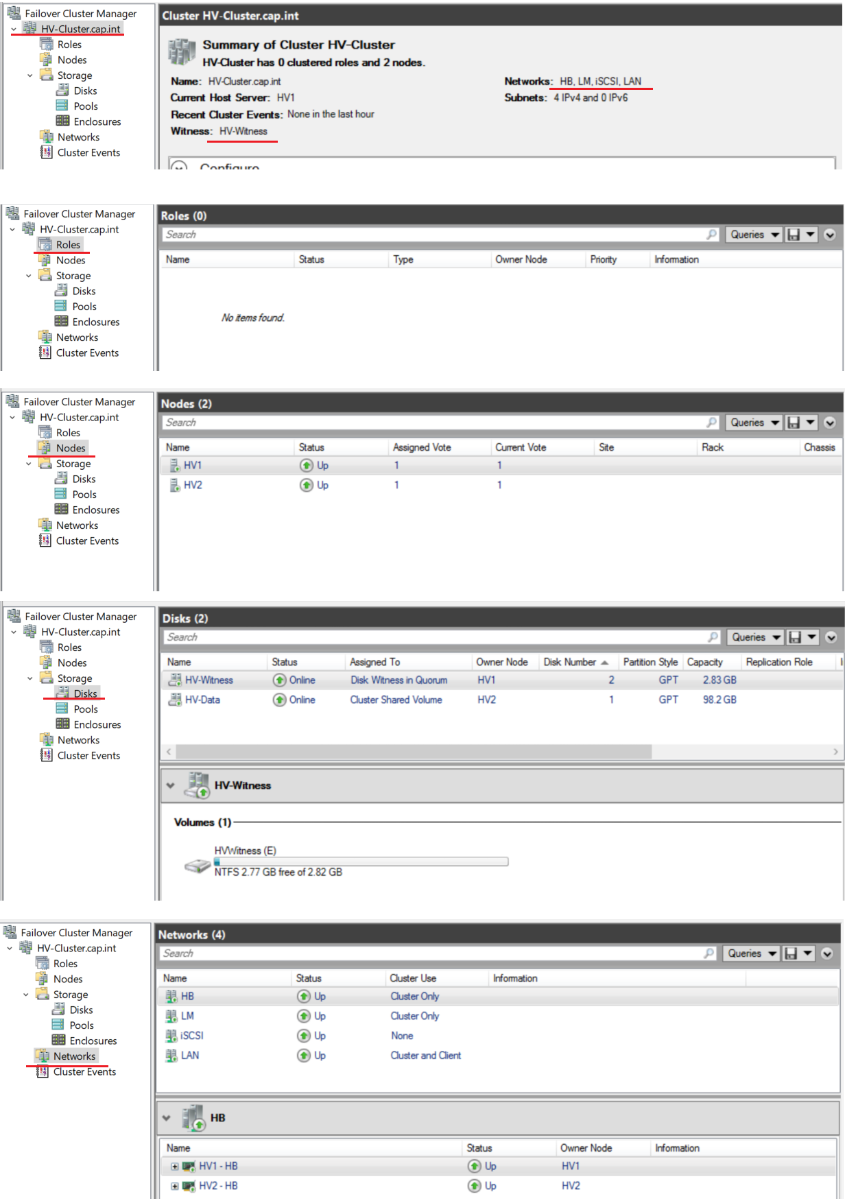
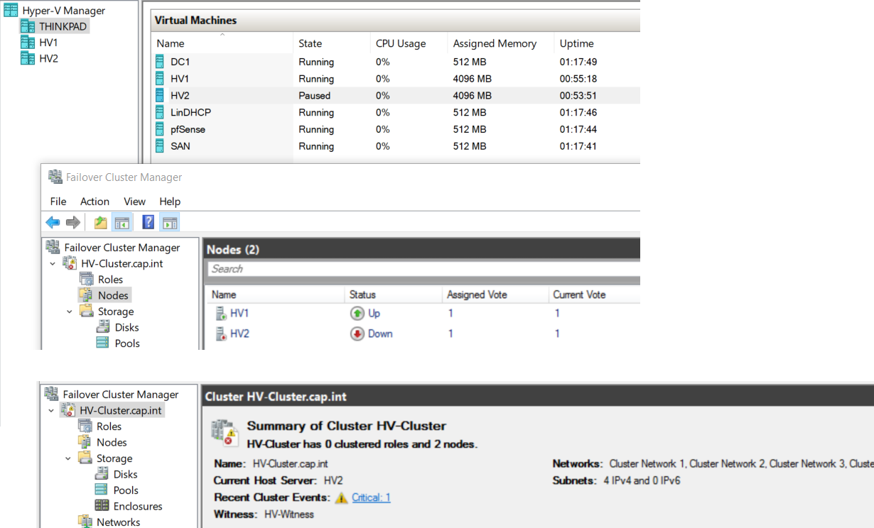
- View HV-Cluster.cap.int
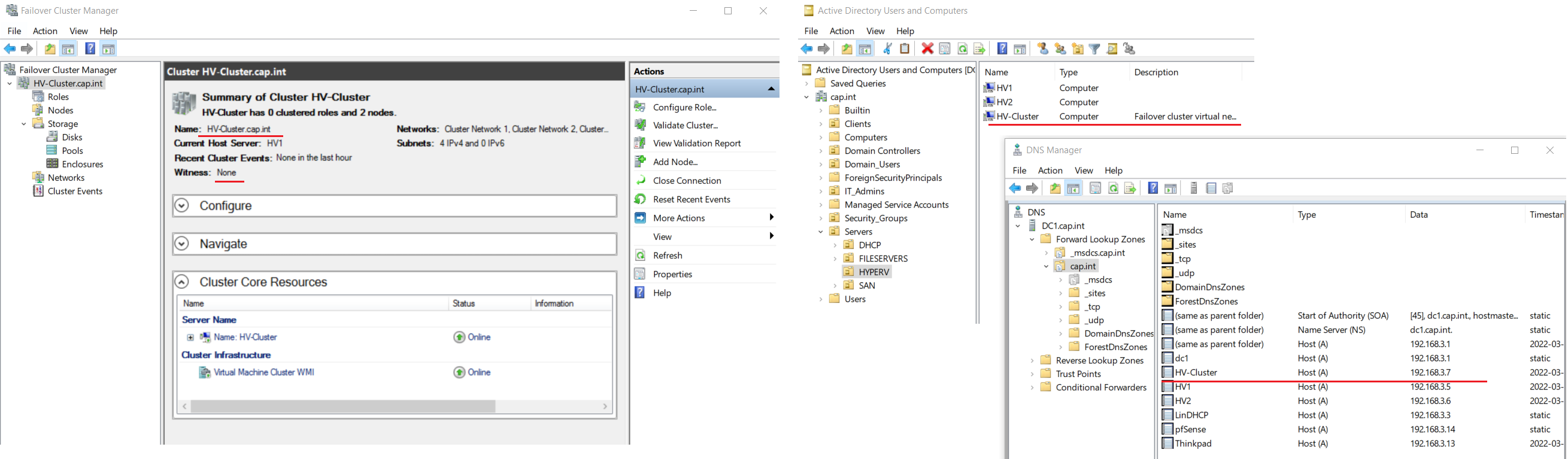
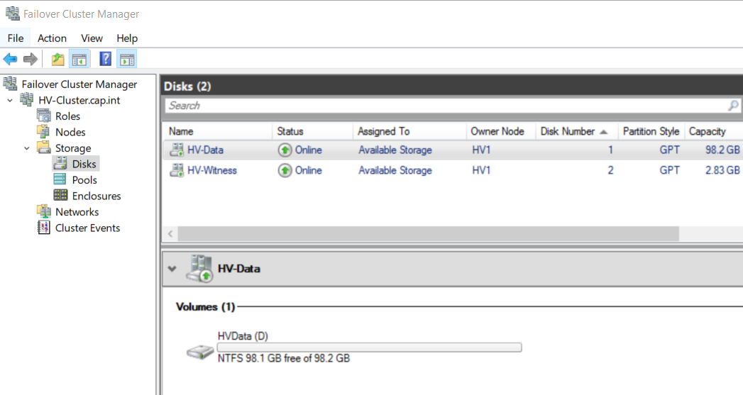
- In Failover Cluster Manager navigate to HV-Cluster.cap.int > Storage > Disks
- Click Add Disk and add both Cluster Disk 1 and 2 (HVdata and Quorum)
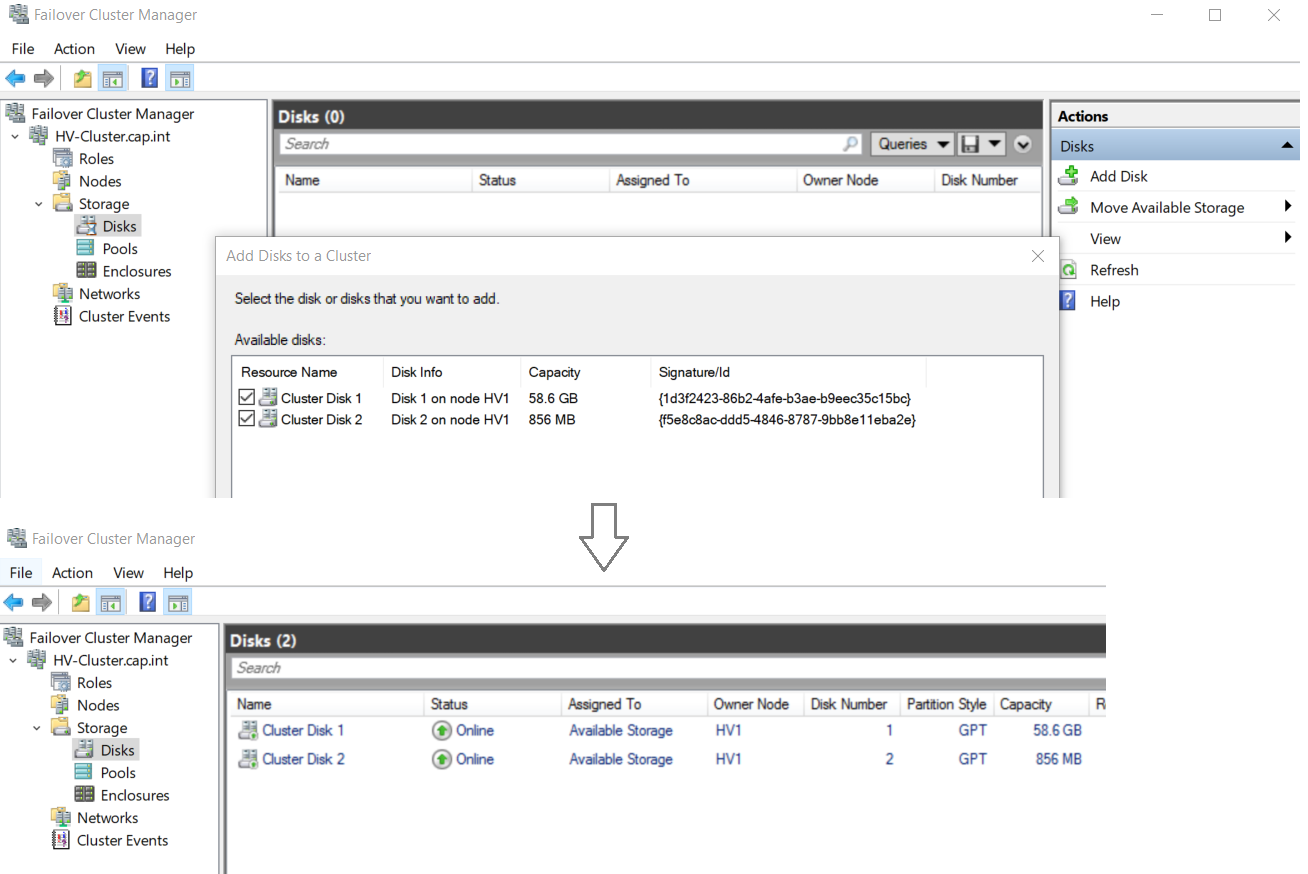
- Rename the disks from Cluster Disk # to “HV-Data” and “HV-Witness”
- Right click the disk HV-Data > Select Add to Cluster Shared Volumes
- Cluster Shared Volumes (CSV) enable multiple nodes in a Windows Server failover cluster to simultaneously have read-write access to the same LUN (disk) that is provisioned as an NTFS volume
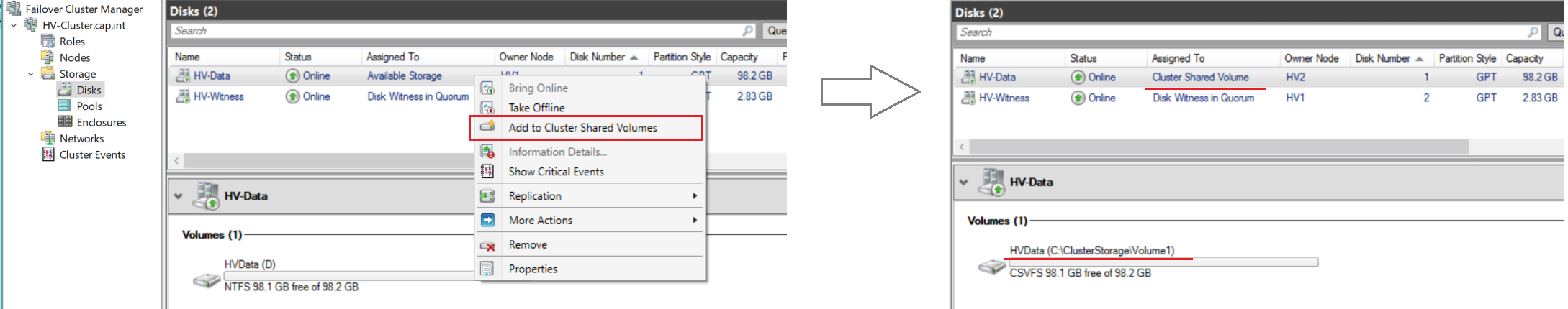
HVData D:\ is now in the C:\ drive 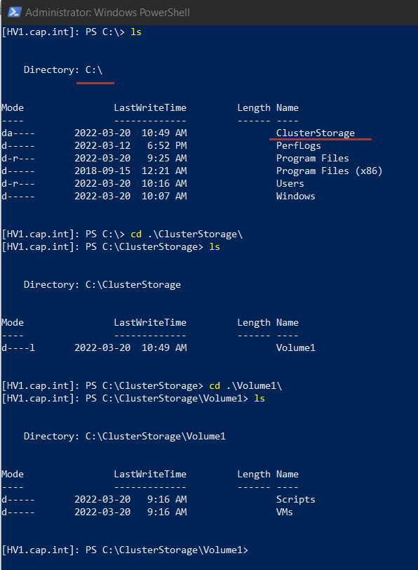
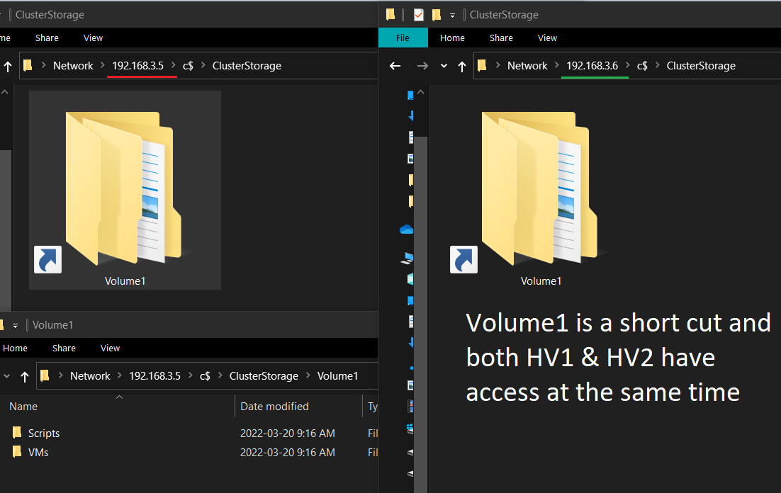
- Cluster Shared Volumes (CSV) enable multiple nodes in a Windows Server failover cluster to simultaneously have read-write access to the same LUN (disk) that is provisioned as an NTFS volume
- Right click HV-Cluster.cap.int > More Actions > Click Configure Cluster Quorum Settings....
- Complete the Configure Cluster Quorum Wizard with the following:
- Select Quorum Configuration Option: Click Select the quorum witness
- Select Quorum Witness: Click Configure a disk witness
- Configure Storage Witness: Click HV-Witness
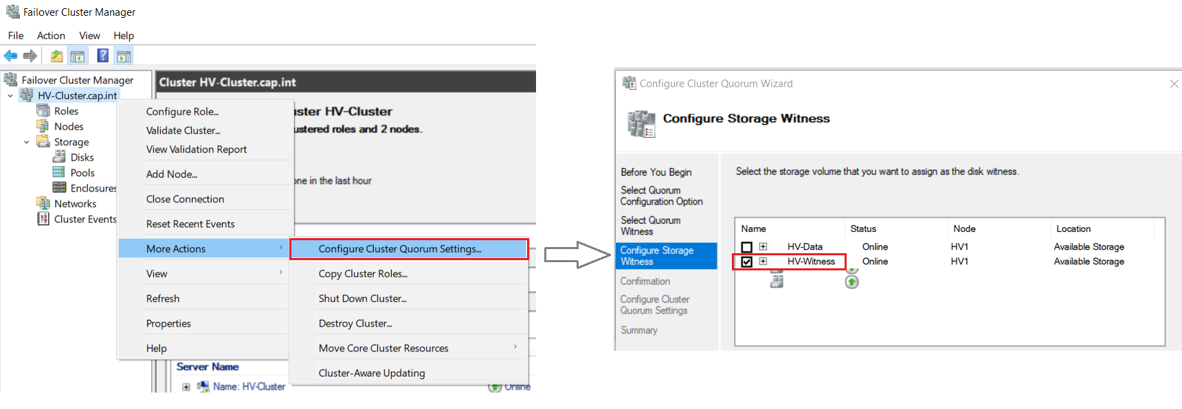
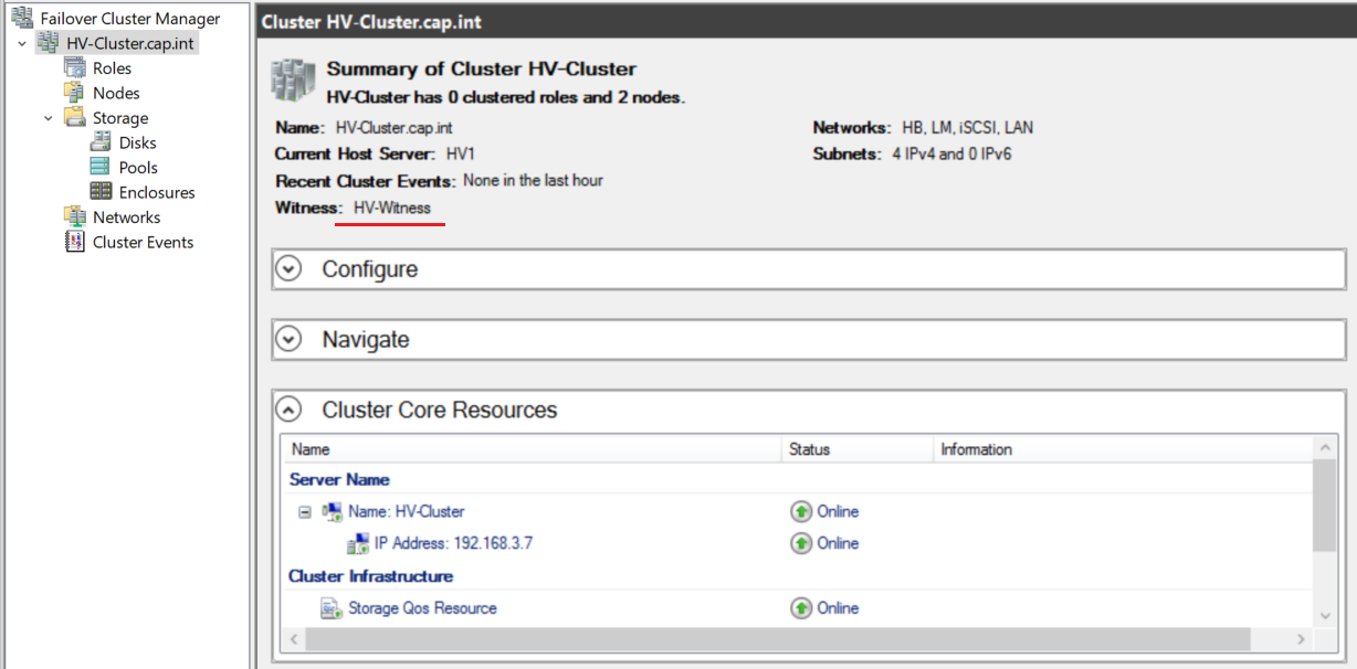
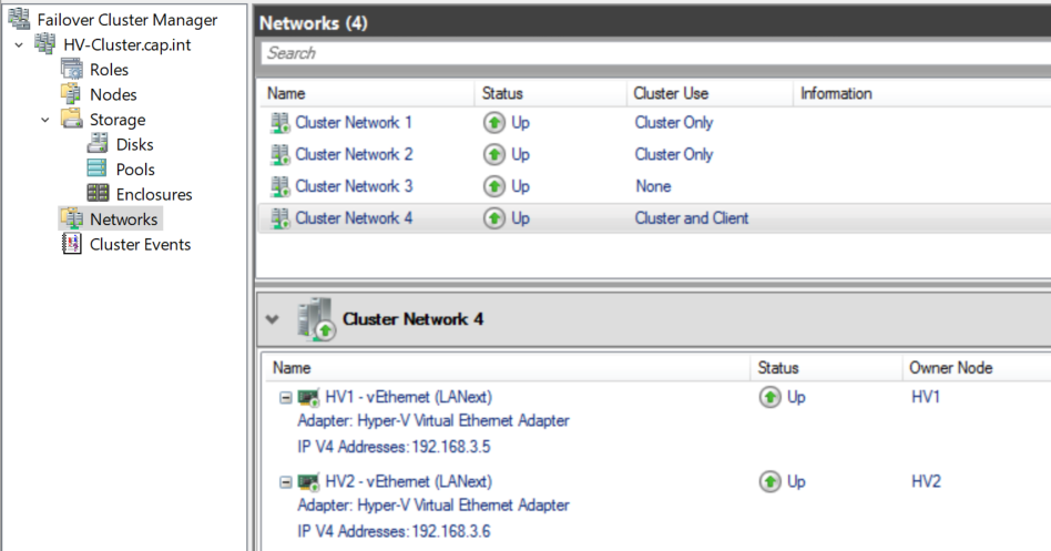
- In Failover Cluster Manager > Networks > Rename the networks from Cluster Network # to the proper network name
- (Optional) Click through all the HV-Cluster.cap.int options
- (Optional) Run
ipconfigon HV1 and HV2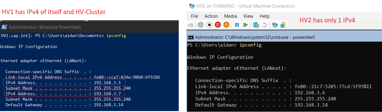
- (Optional) View Server Manager > click Refresh > and notice that HV-Cluster is added automatically
9.6 Test Live Migration and Hyper-V Failover
9.6 Test Live Migration and Hyper-V Failover
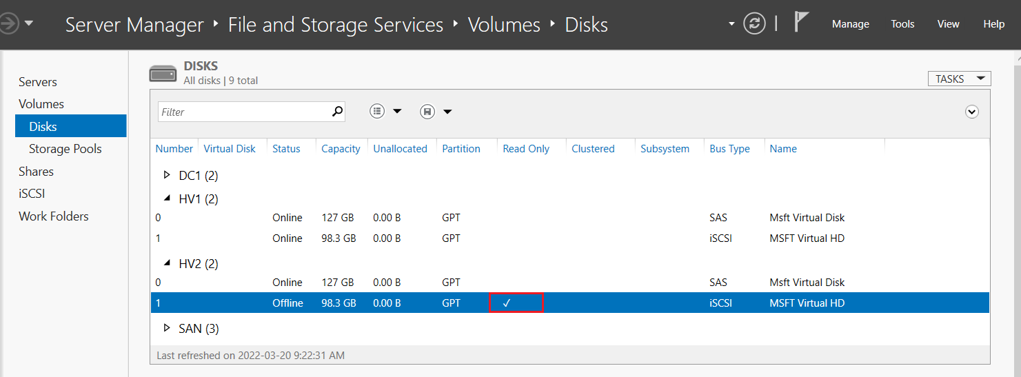
- Test failover clustering by pausing HV1 on Thinkpad’s Server Manager > verify the cluster remains > then resume HV1
- Test failover clustering by pausing HV2 on Thinkpad’s Server Manager > verify the cluster remains > then resume HV2
- Go to Hyper-V Manager on Thinkpad > Click HV2 > Hyper-V Settings
- Change the default locations from D:\ to the ClusterStorage on C:\
- Virtual Hard Disks:
C:\ClusterStorage\volume1\vms\vhdx\
- Virtual Machines:
C:\ClusterStorage\volume1\vms\
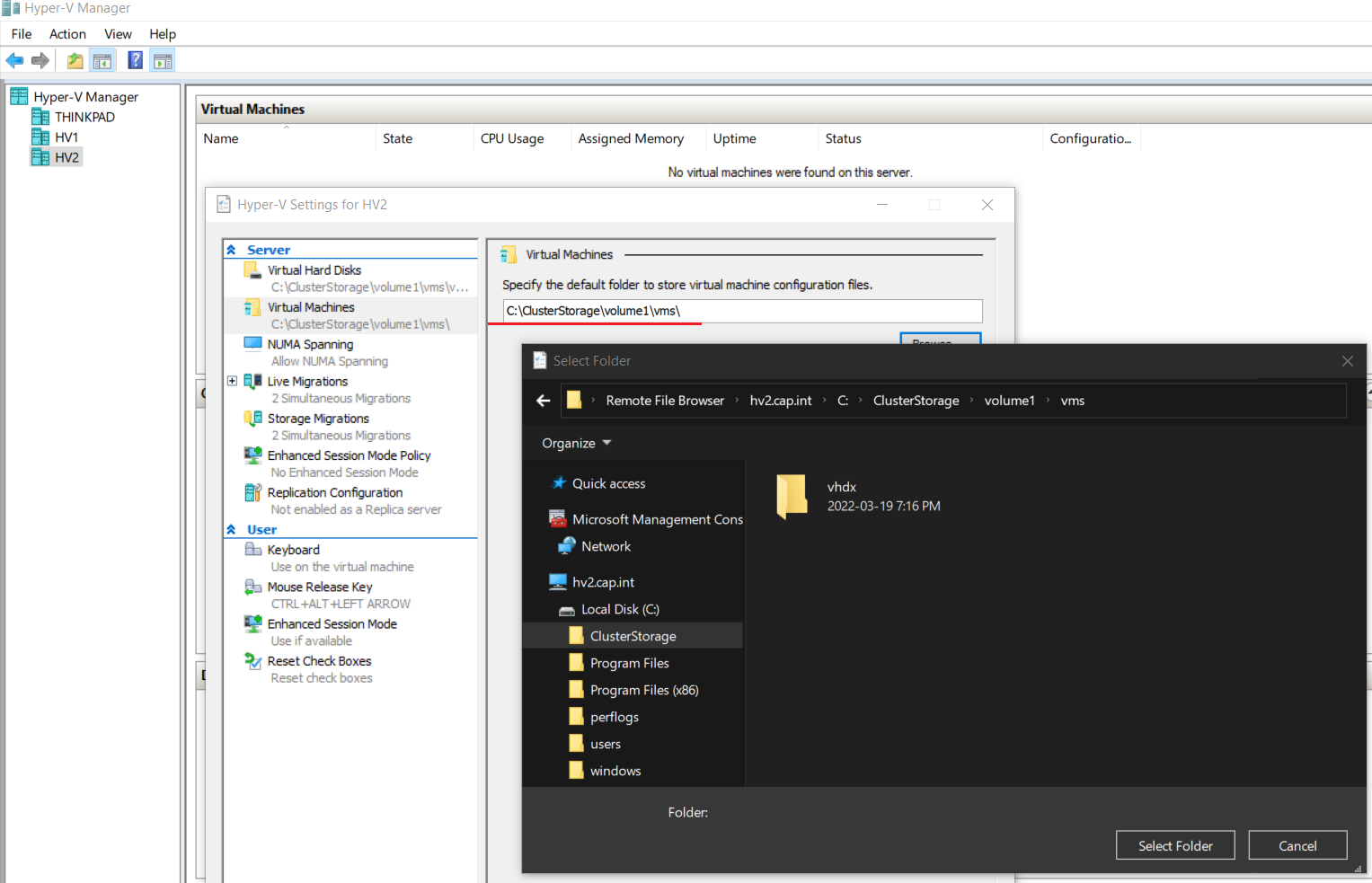
- Virtual Hard Disks:
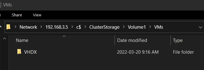
- Copy over the ParentServer2019-Core.vhdx file from Thinkpad to
\\192.168.3.5\c$\ClusterStorage\Volume1\VMs\VHDX(or to\\192.168.3.6as both have access)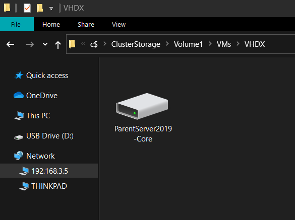
- Go to Roles > Click Virtual Machines... > New Hard Disk... > create a differencing vhdx named ‘File1’
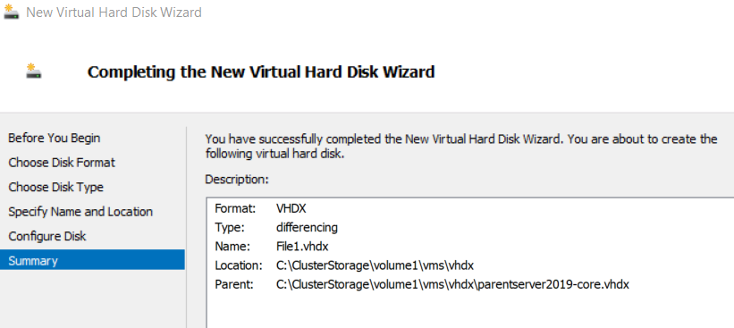
- In Roles > Virtual Machines... > Click New Virtual Machine... > Create a VM named “File1” with 1024 MB Static Memory that is connected to the child differencing disk and the LAN external switch
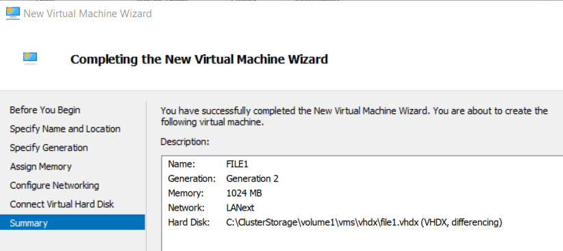
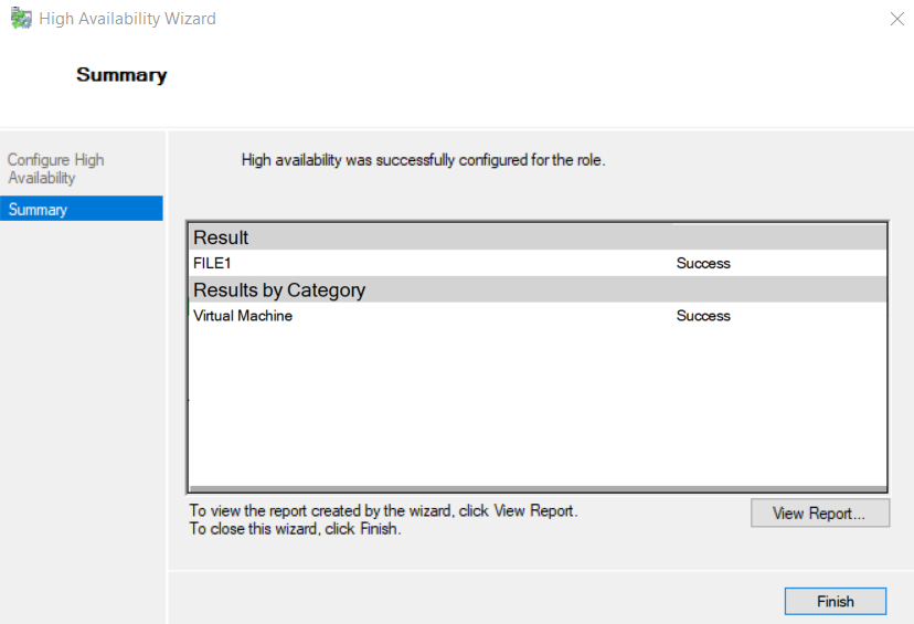
- Notice that when the VM is created, the High Availability Wizard automatically appears and runs
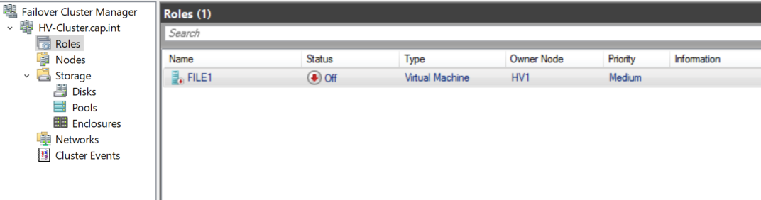
- Within Failover Cluster Manager > Roles > right-click File1 > Connect and start
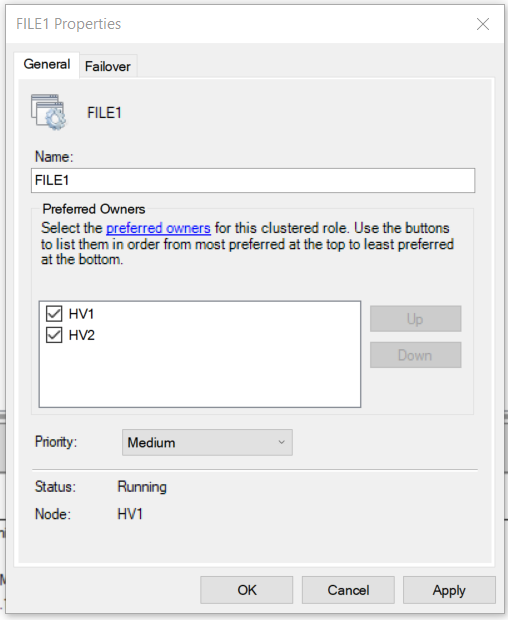
- Set FILE1’s property preferred owners to be both HV virtual machines
- Test live migration by going clicking Move > Live Migration > Select Node.... > Select the other HV VM
- When complete notice that the Owner Node changes to the other HV virtual machine
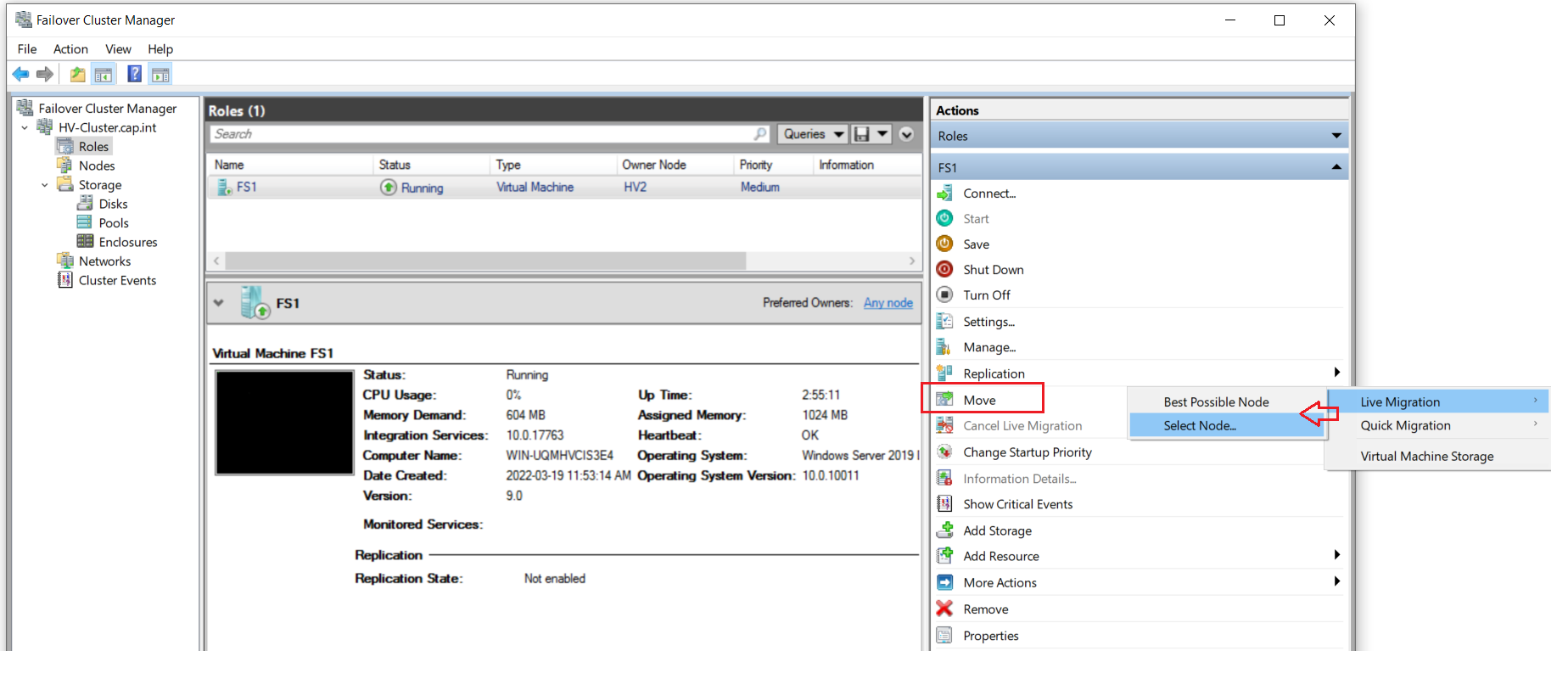
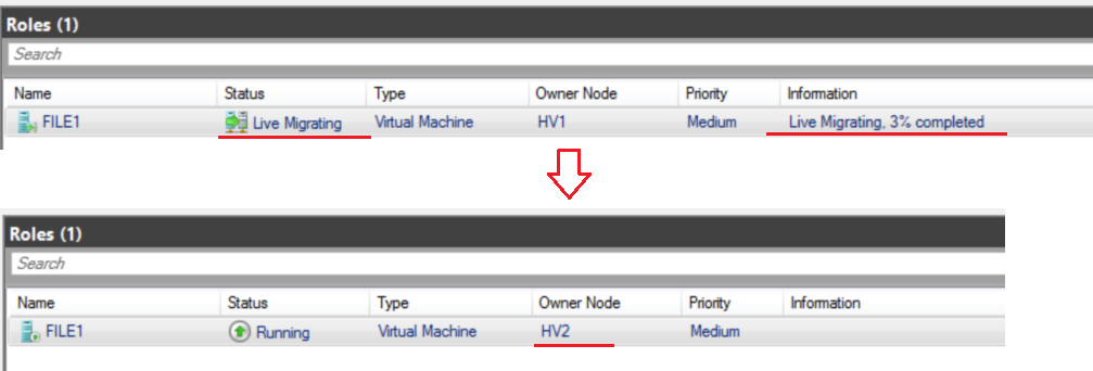
- When complete notice that the Owner Node changes to the other HV virtual machine
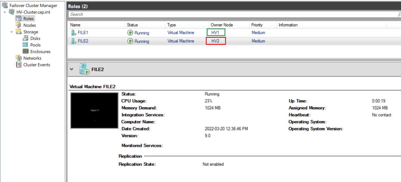
- Create another VM named ‘FILE2’ on the HV# that is not in use > verify that a separate role is created and that the VM’s boot and run while on different nested Hypervisors
10.0 File Server Cluster
Within the nested Hyper-V cluster create 2 VM’s for FILE1 and FILE2. The machines will be clustered together for failover and use a VHD Set for the file server role which will have a SMB share.
10.1 Server Role, Hardware, and HB Network Setup
10.1 Server Role, Hardware, and HB Network Setup
- ⏲ Checkpoint DC1 and name it “Before FS and cluster”
- On FILE1 and FILE2 run the post install tasks from Appendix F
- ❗ for spaces and line breaks the script has
^Mthis is ok and it will run as expected
- ❗ for spaces and line breaks the script has
- Complete the verification checks as per Appendix G
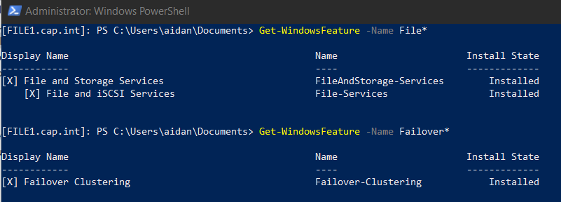
- On FILE1 and FILE2 install the role File Server and feature Failover Clustering
- In Failover Cluster Manager navigate to Roles > Under the Actions panel click Virtual Machines... > Select New Hard Disk..
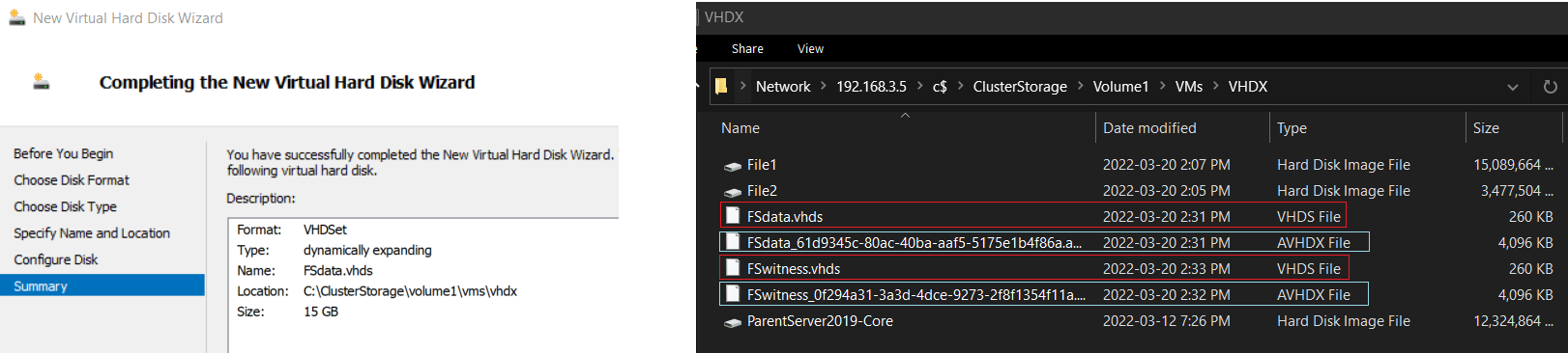
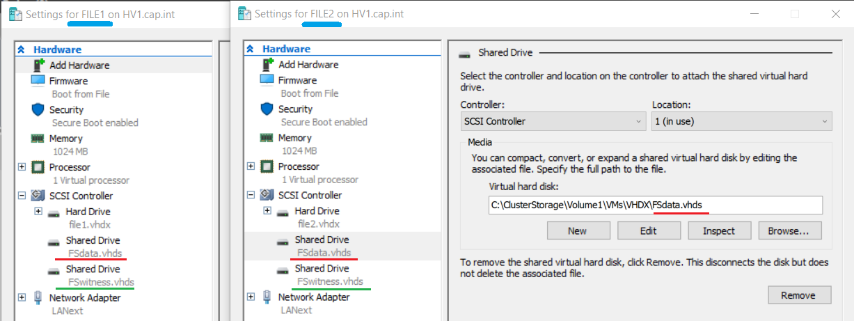
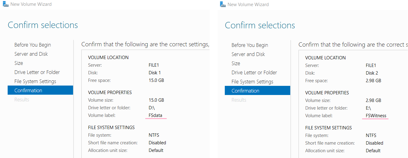
- Complete the Virtual Hard Disk Wizard with the following to create a VHD Set:
- Format: VHDSet
- Type: Dynamically Expanding
- Name: “FSdata.vhds”
- Location: The cluster storage volume
- Size: 15 GB
- ❗ If a Fixed disk is created instead it may take up to 20 minutes to create - choose dynamic
- Create a 2nd VHDS named “FSwitness” that is 3GB in size
- In File Explorer view the new VHDS file and notice that there are 2 files per set
- Virtual machines connect to the .VHDS file and data is stored in the .AVHDX file
- .vhds is a configuration file that contains metadata, and is used for maintaining simultaneous access to the disk from multiple cluster nodes.
- .avhdx (“automatic .vhdx”) is an actual virtual disk where the data resides. It can be fixed or dynamic.
- From PowerShell on HV1 (or HV2) run the following command to attach the VHD Set to the FILE machines :
Add-VMHardDiskDrive -VMName FILE2 -Path "C:\ClusterStorage\Volume1\VMs\VHDX\FSdata.vhds" -SupportPersistentReservations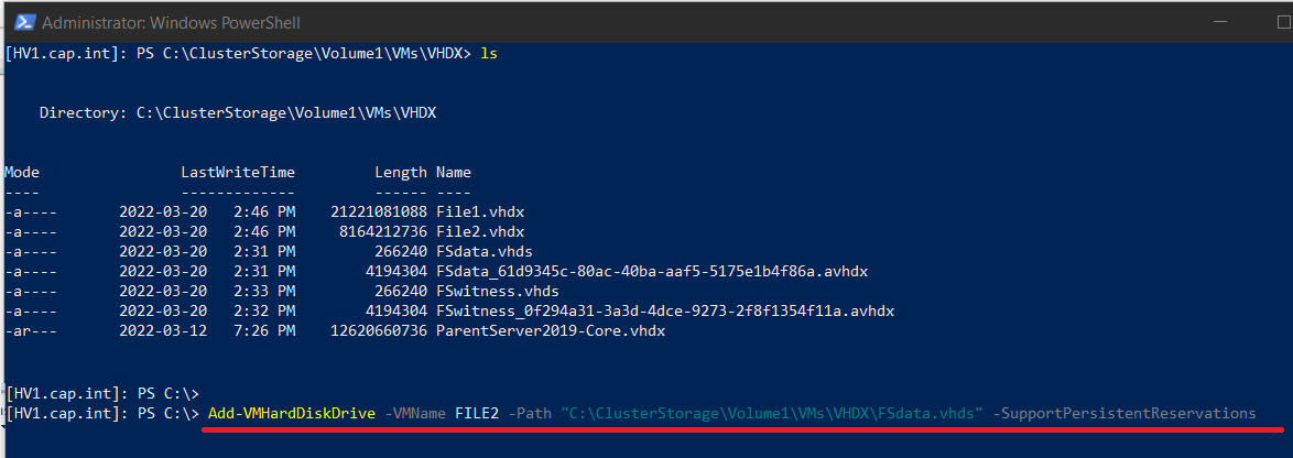
- Repeat so both HV1 and HV2 has FSdata.vhds & FSwitness.vhds
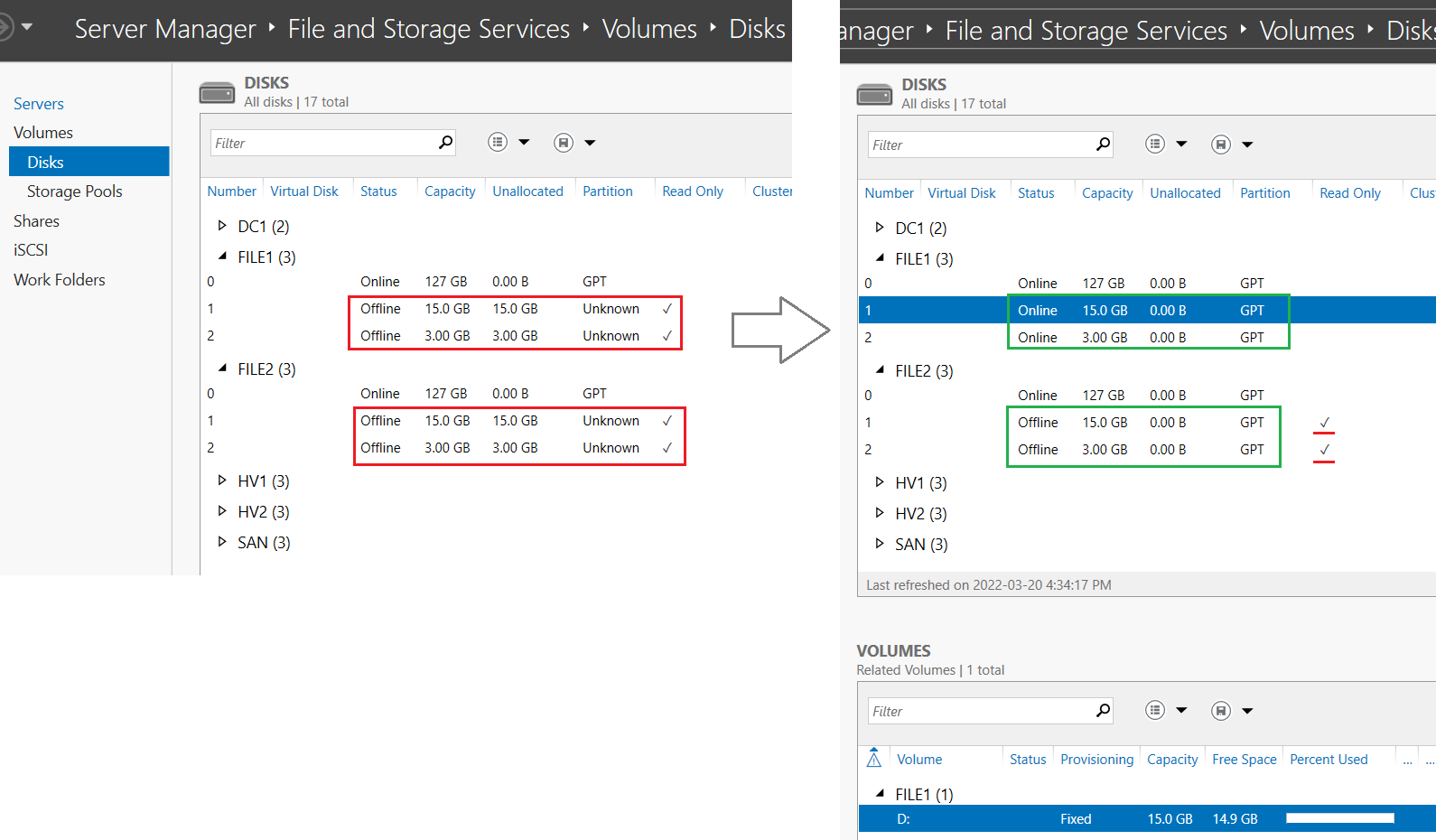
- From Server Manager navigate to File and Storage Spaces > Volumes > Disks
- Bring FSdata.vhds & FSwitness.vhds online, initialize, and create volumes with the file system NTFS
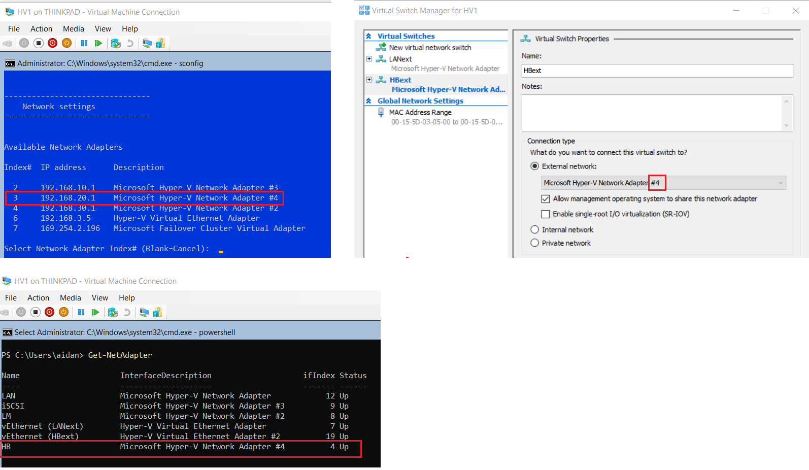
- On HV1 view the available network adapters in
sconfigor PowerShellGet-NetAdapter
- View which adapter (by IP or adapter name) is connected to the HB network & the corresponding interface description number Hyper-V Network Adapter#
- In the Hyper-V Manager for HV1 > Virtual Switch Manager... > Create a new virtual network switch:
- Switch Type: External
- ❗ Select the Microsoft Hyper-V Network Adapter # that corresponds to the HB network
- Name: HBext
- Repeat on HV2 to create another external switch
- On Hyper-V Manager for Thinkpad > Open the settings for HV1
- Expand the HB Network Adapter > Advanced Features > Check Enable MAC address spoofing
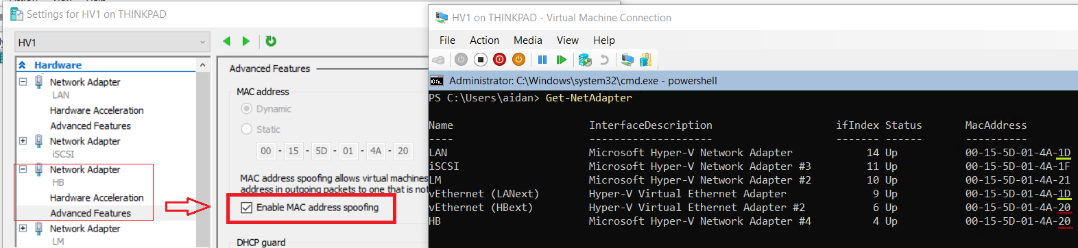
❗ MAC Spoofing must be enabled or the FILE machines will not be able to communicate outside of the nested Hyper-V host
- Repeat on HV2 to enable MAC spoofing on the HB adapter
- On FILE1 & FILE2 from
sconfigor PowerShell set the following:IPv4 FILE1 192.168.20.3 IPv4 FILE1 192.168.20.4 Subnet 255.255.255.248 NetAdapter Name HBext
- Verify connectivity on the HB network
192.168.20.0 /29by sending pings from FILE1 to FILE2 and vice versa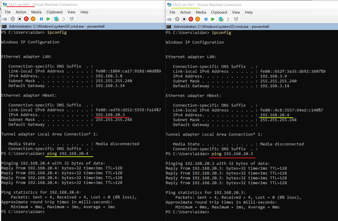
10.2 Create and Configure the Cluster
10.2 Create and Configure the Cluster
- From Failover Cluster Manager validate the configuration for FILE1 and FILE2 by running all tests
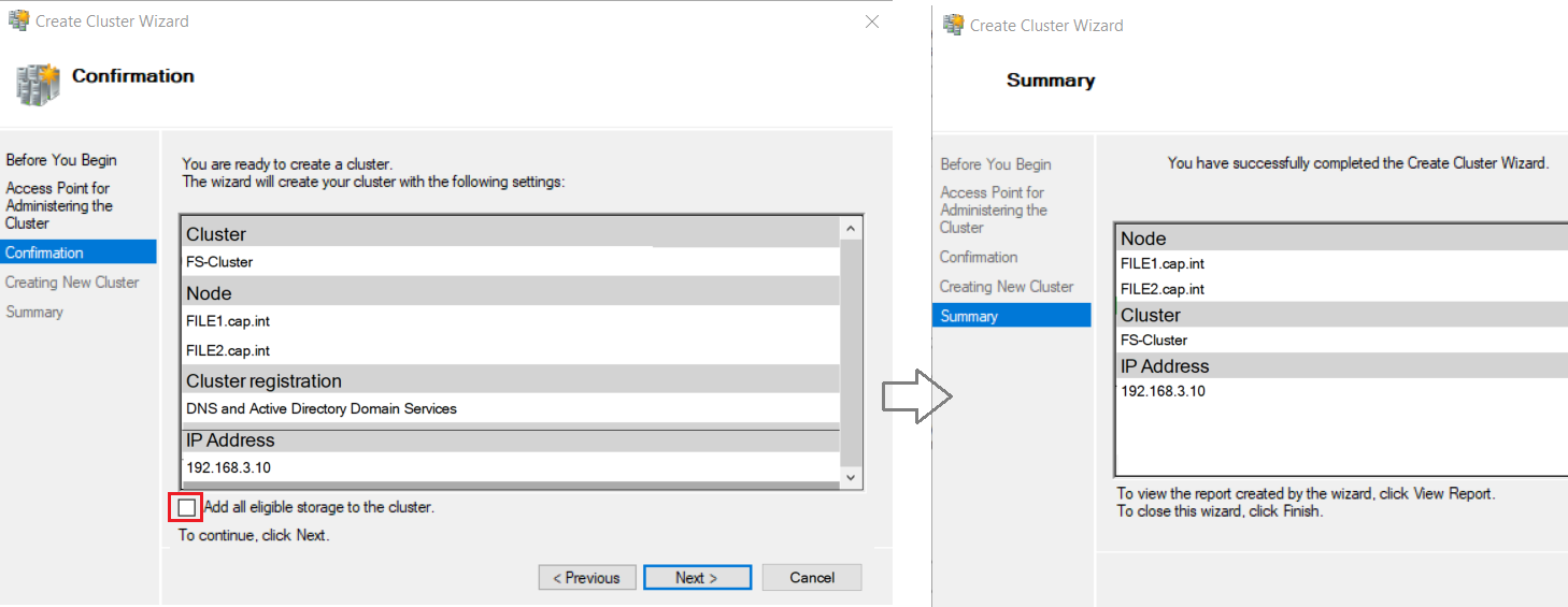
- Complete the Create Cluster Wizard with the following:
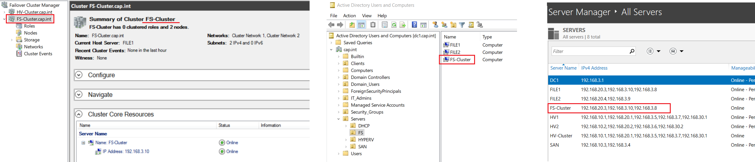
- Cluster Name: “FS-Cluster”
- IP Address: 192.168.3.10
- Add all eligible storage to the cluster: Uncheck
- View results - notice that there are 2 clusters connected in the manager HV-Cluster and FS-Cluster
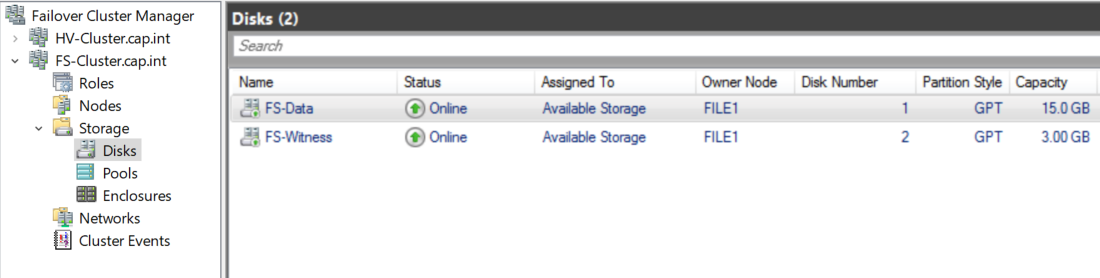
- From Storage > Disks > Add both VHDS to the cluster & rename
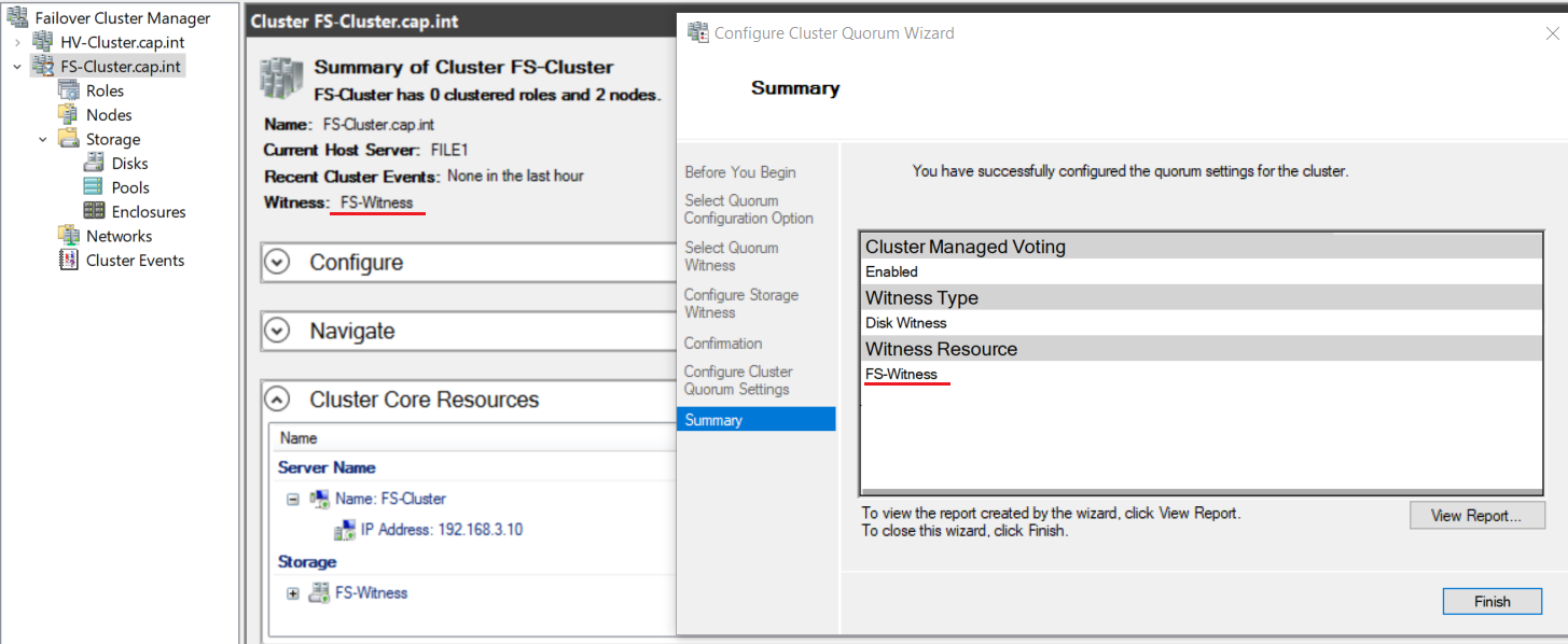
- Configure the cluster quorum and add the disk FS-Witness to be the disk witness resource
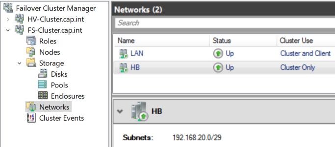
- Rename the networks in FS-Cluster to “LAN” and “HB”
10.3 Allow CNO FS-Cluster to Create Computer Objects in AD DS
10.3 Allow CNO FS-Cluster to Create Computer Objects in AD DS
- ❗ Without this step, the File Server role will install but will be offline and have errors because FS will not be created because the Cluster Name Object (CNO) FileServerCluster does not have permission to create computer objects.
The file server role will add but have a failed status without editing the FS OU Permission Properties
- From Server Manager > Right-click DC1 > Open Active Directory Users and Computers (ADUC)
- On the View menu taskbar check Advanced Features so it is selected
- Right-click the FS OU where the FS-Cluster CNO (Cluster Name Object) is located > select Properties
- On the Security tab, select Advanced > Add
- In the Permission Entry window click Select a principal > Object Types > Select Computers
- Add the object FS-Cluster
- In the Permission Entry dialog box set the following:
- Type: Allow
- Applies to: This object and all descendant objects
- Permissions: Select Create Computer objects
10.4 Add the File Server Role
10.4 Add the File Server Role
- In Failover Cluster Manager navigate to > FS-Cluster.cap.int > Roles > Click Configure Role...
- Create the role File Server with the following:
- Client Access Point: Name = “FS” & IP=
192.168.3.11
- Storage Disk: FS-Data
- Client Access Point: Name = “FS” & IP=
- View results
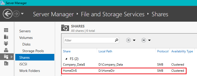
10.5 Create File Share
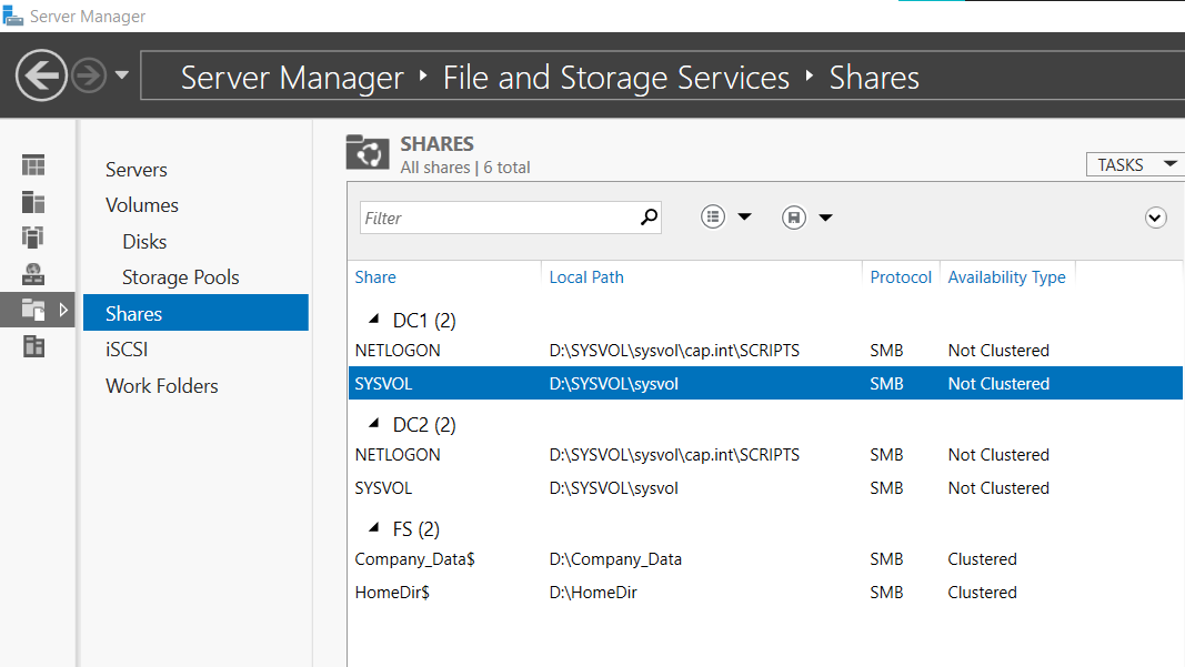
10.5 Create File Share
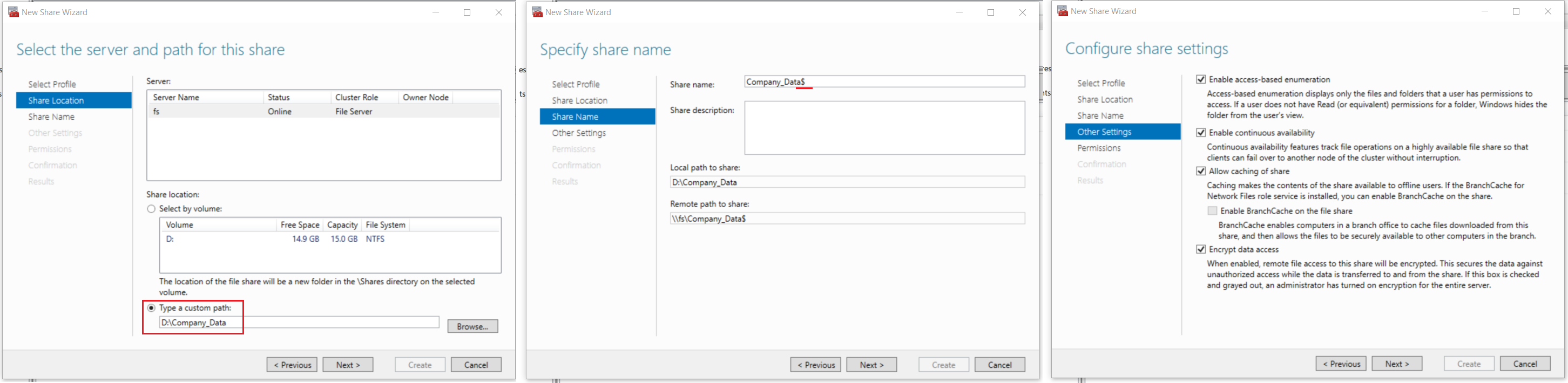
- Click on the File Server object FS in the cluster roles > Click Add File Share to open the New Share Wizard
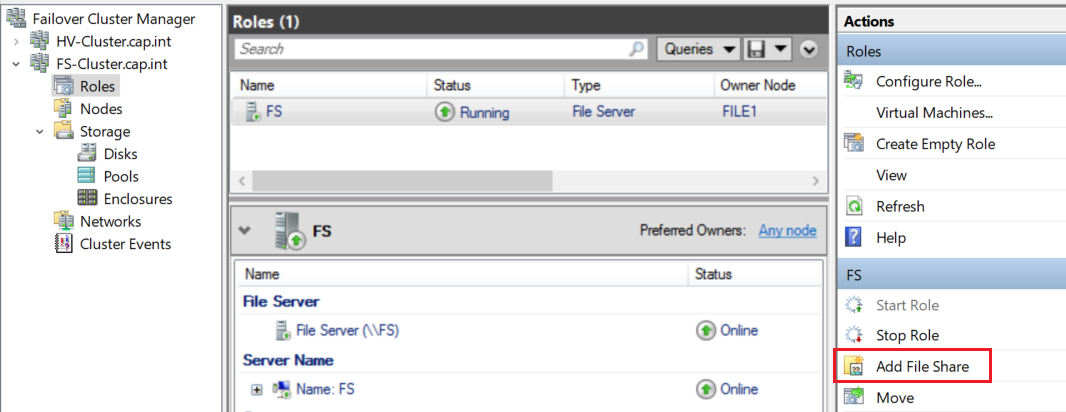
- Complete the first 4 steps in the wizard as follows:
- Select Profile: SMB Share - Quick
- Share location: Click Type a custom path and create and select the directory “Company_Data”
- Share Name: Add the
$after the share name so the remote path shows as\\fs\Company_Data$
- Configure share settings: Select all four options
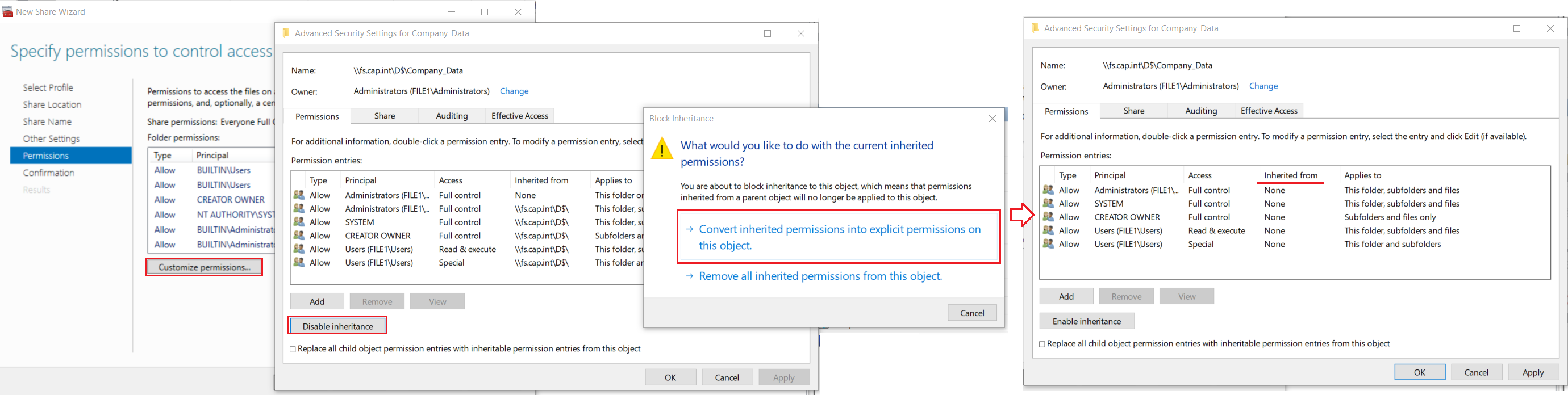
- On the Permissions step click Customize Permissions.. > Disable inheritance > click Convert inherited permissions into explicit permissions on this object
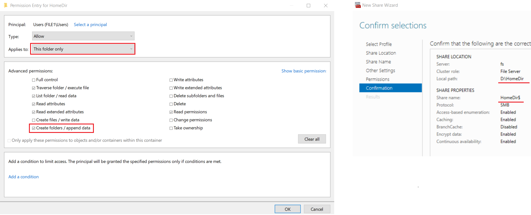
- Select entry for Principal Users (FILE1\Users) with Access = Special > click Remove
- Select entry for Principal Users (FILE1\Users) with Access = Read & Execute > Change the setting ‘Applies to’ to This folder only
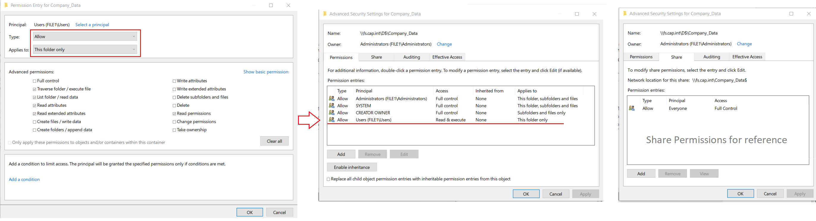
FILE1 user permissions & result for the advanced security settings tab Permissions and Share
- Confirm the settings in the wizard > click Create
- From Thinkpad’s file explorer navigate to the share
\\fs\Company_Data$
- Pause the owner VM to test the file share failover clustering, verify the share can still be accessed
- Set the memory on FILE1 and FILE2 to 512 MB
11.0 Create AGLDP Structure and GPOs
Create an AGDLP Security group structure for cap.int. Account, Global Groups (Role Based), Domain Local (tied to Read/Write (RE) or Read/Execute (RE) permissions), Permissions. Create a Group Policy Object (GPO) that maps the file share from step 10.5 to the domain user’s computer. Create another GPO to redirect the Desktop and Document folders to a new file share.
11.1 Setup AGDLP File Permissions for the Share
11.1 Setup AGDLP File Permissions for the Share
- Open Active Directory Users and Computers and go to the OU Security_Groups
- From ADUC or PS, in the OU IT_Groups create the following Global Groups & add the domain user as a member follows:
Security Group Name Group Scope Domain Member IT_Managers_G Global Bob Lo IT_ServiceDesk_G Global Dan Wu 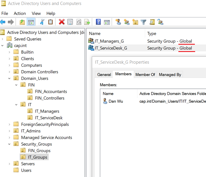
#Create Security Group
Get-Command -Module ActiveDirectory
New-ADGroup "IT_Managers_G" `
-Path "OU=IT_Groups,OU=Security_Groups,DC=cap,dc=int" `
-GroupCategory Security `
-GroupScope Global `
-PassThru –Verbose

#Add Member to Group - Phil.Gibbins
Add-ADGroupMember -Identity "IT_Managers_G" -Members bob.lo

#View group members to verify Phil was added, can also refresh in AD
Get-ADGroupMember -Identity "IT_Managers_G"
- From ADUC or PS, in the OU FIN_Groups create the following Global Groups & add the domain user as a member follows:
Security Group Name Group Scope Domain Member FIN_Accountants_G Global Amy Li FIN_Controllers_G Global Sam Hu
- In the OU IT_Groups create the following Domain Local Groups & add global group as a member follows:
Security Group Name Group Scope Member IT_Management_RW_DL Domain Local IT_Managers_G IT_ServiceDesk_RW_DL Domain Local IT_ServiceDesk_G 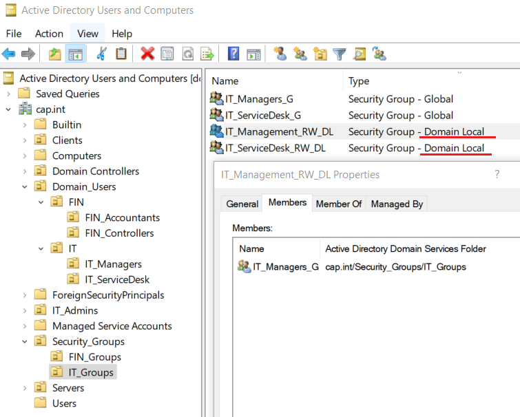
- In the OU FIN_Groups create the following Domain Local Groups & add the global group as a member follows:
Security Group Name Group Scope Member FIN_Accounting_RW_DL Domain Local FIN_Accountants_G FIN_Accounting_RE_DL Domain Local FIN_Accountants_G FIN_Controllers_RW_DL Domain Local FIN_Controllers_G 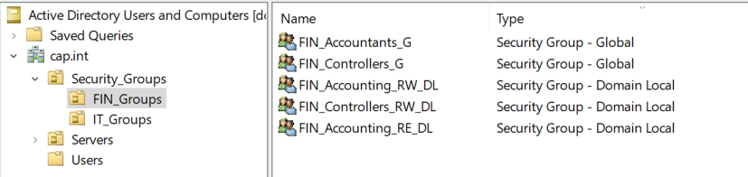
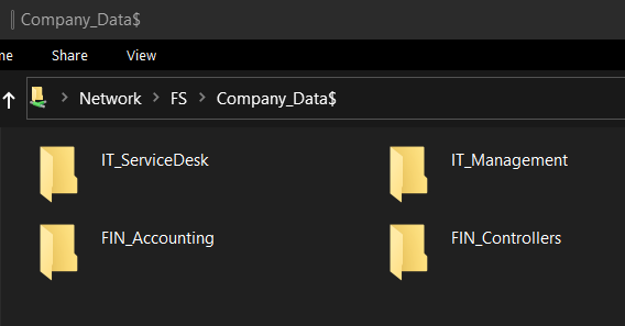
- On Thinkpad open the file explorer and access the share
\\FS\Company_Data$
- Create 4 directories in the share - “IT_ServiceDesk”, “IT_Management”, “FIN_Accounting”, and “FIN_Controllers”
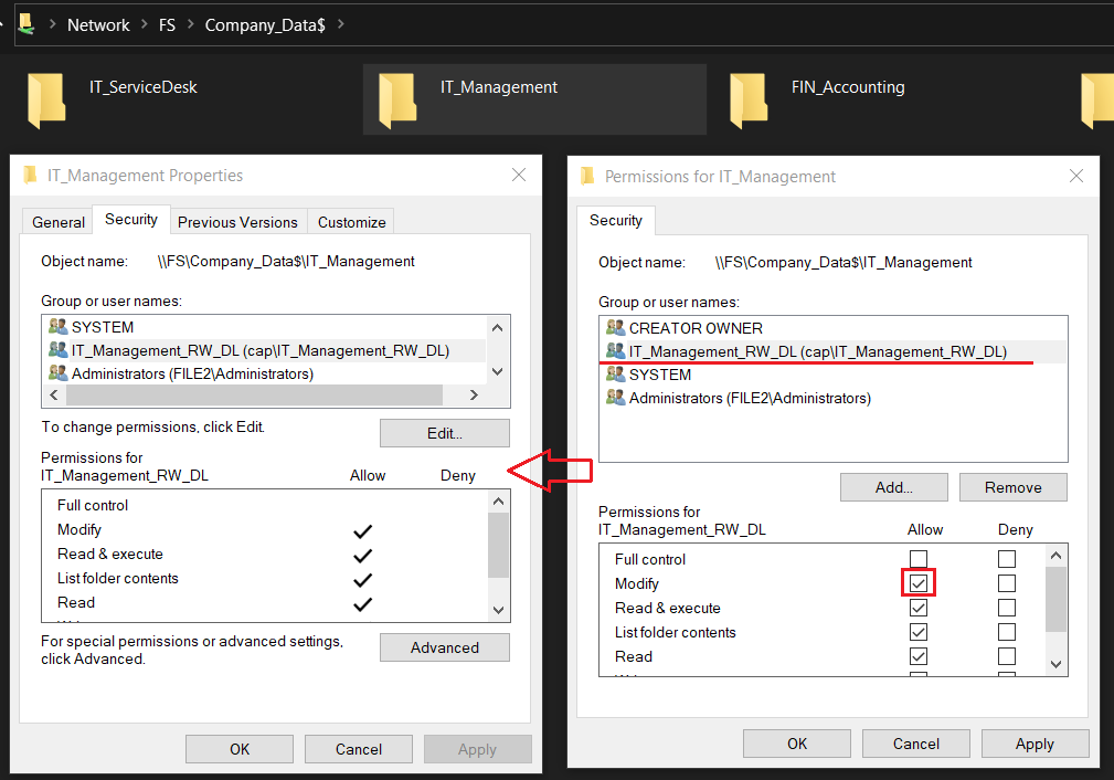
- Right-click the IT_Management directory > select Properties
- Open the tab Security > Click Edit to change permissions > add the group IT_Management_RW_DL
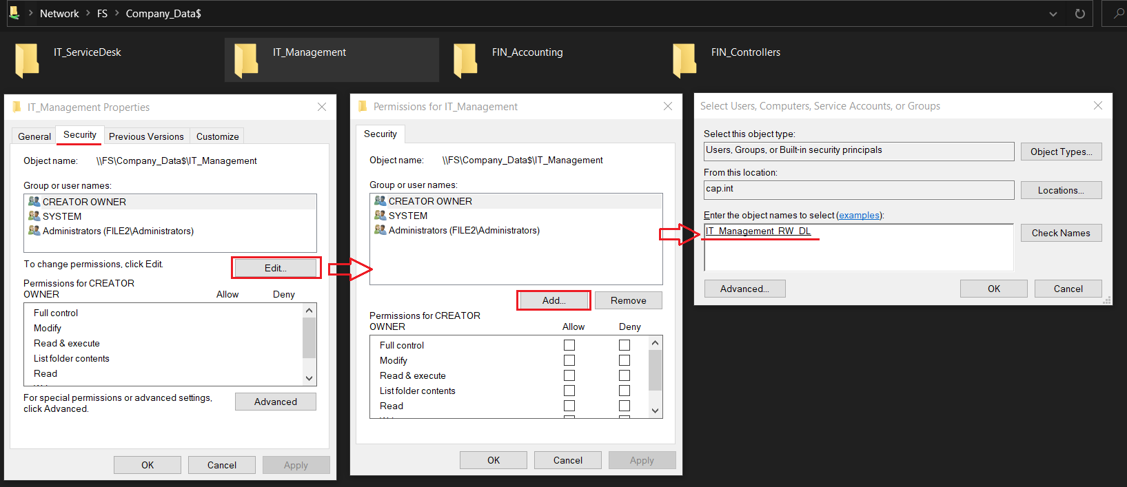
- Give the domain local group Read/Write permissions by checking Modify
- Groups with RW → Modify Permission
- Groups with RE → Read & Execute Permission
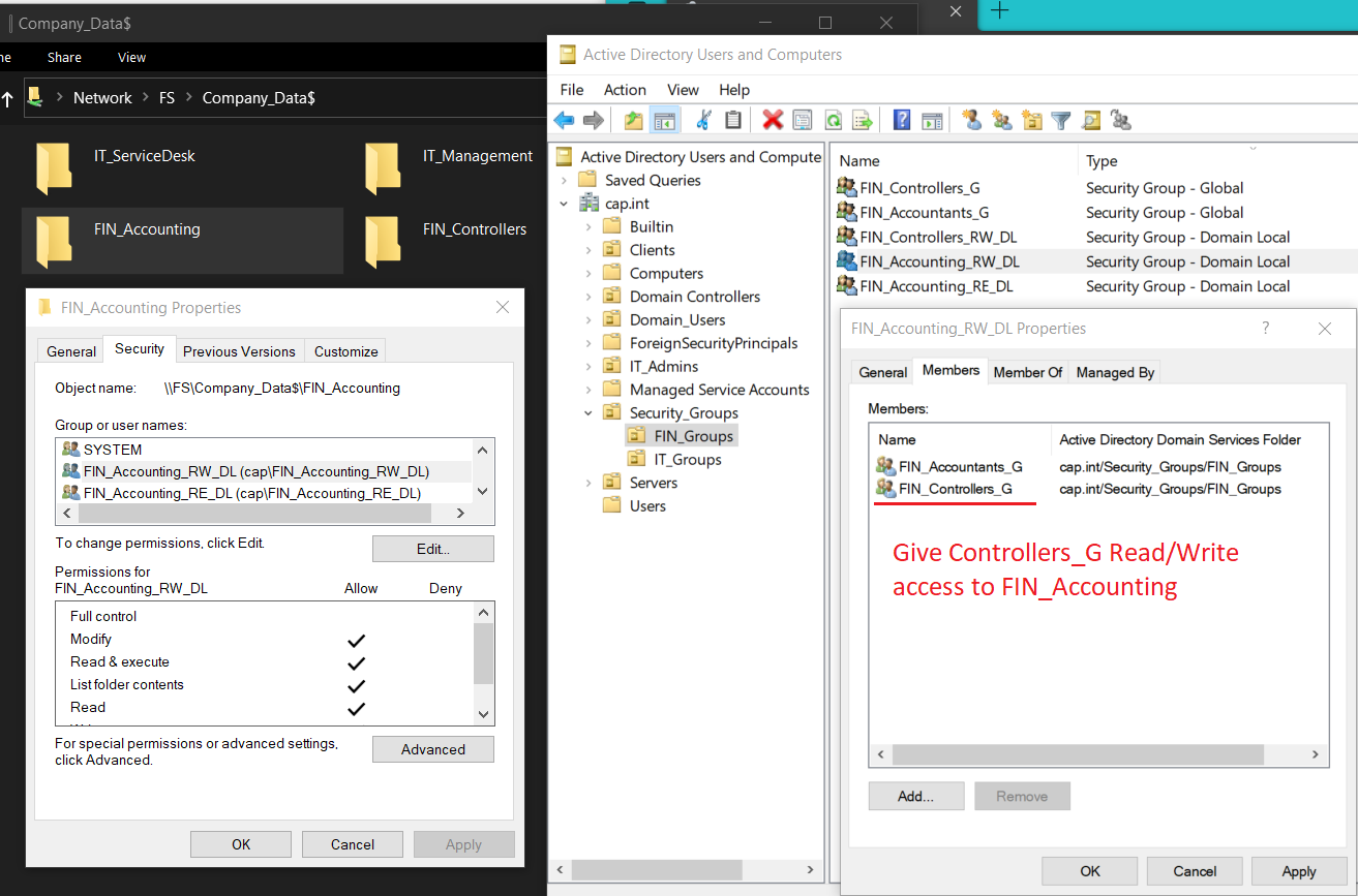
- In ADUC add FIN_Controllers_G as a member of FIN_Accounting_RW_DL to give the controllers Read/Write access of the directory FIN_Accounting as well
- Test the NTFS permission by logging into users amy.li (accountant) and sam.hu (finance controller) and open the share
\\fs\company_data$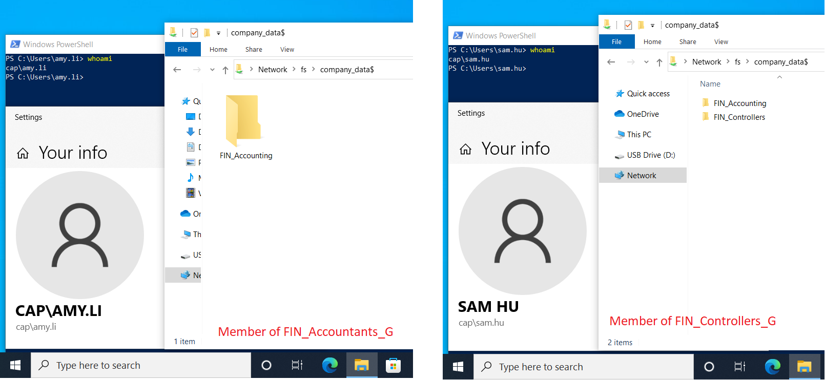
11.2 Create a Mapped Drive GPO
11.2 Create a Mapped Drive GPO
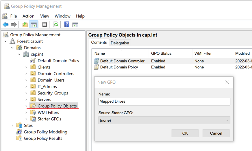
- From Server Manager > Tools > Group Policy Management
- In ‘Group Policy Objects’ > Right click New > Name the GPO “Mapped Drives”
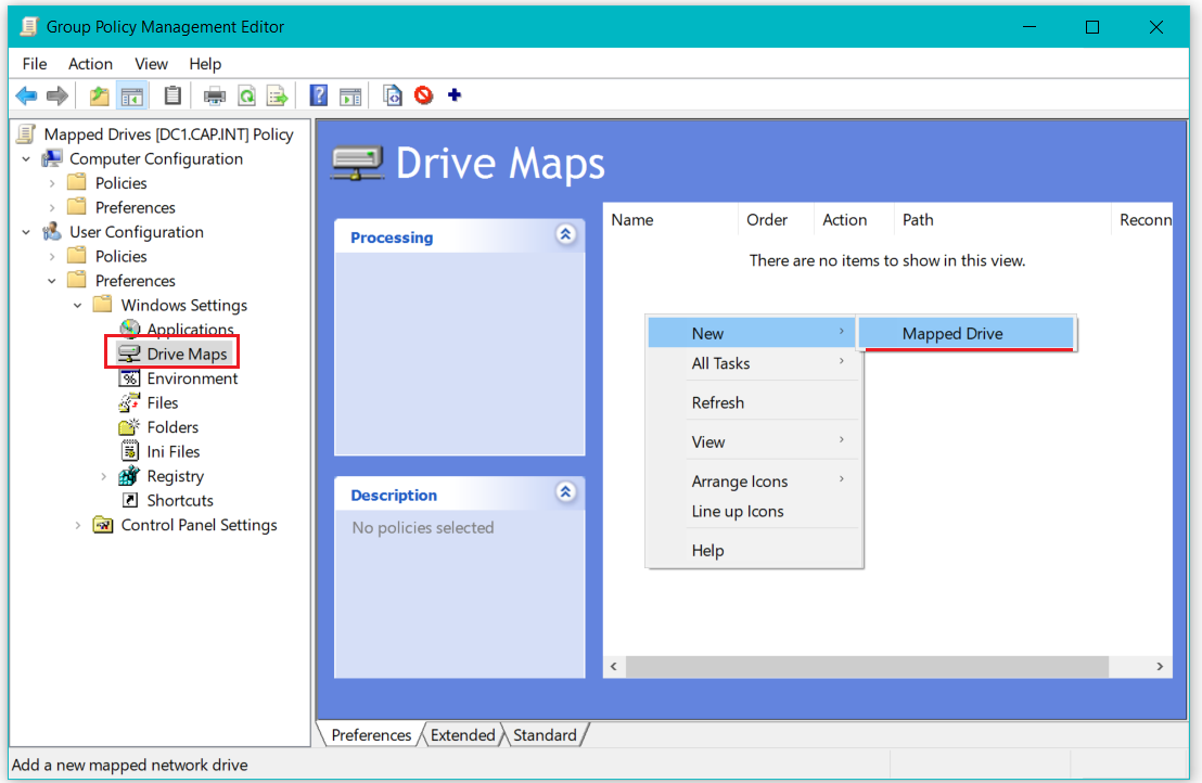
- Right-Click the GPO Mapped Drives > Edit
- In Group Policy Management Editor expand User Configuration > Preferences > Windows Settings > click Drive Maps
- From Drive Maps, right-click New > Mapped Drive
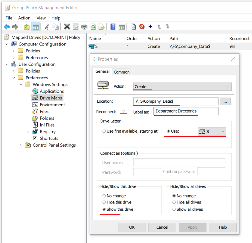
- Create a new drive with the following properties:
- Action: Create
- Location:
\\FS\Company_Data$
- Reconnect: Check
- Label as: “Department Directories”
- Drive Letter: Use “S” for ‘Shared Drive’
- Hide/Show this drive: Select Show this drive
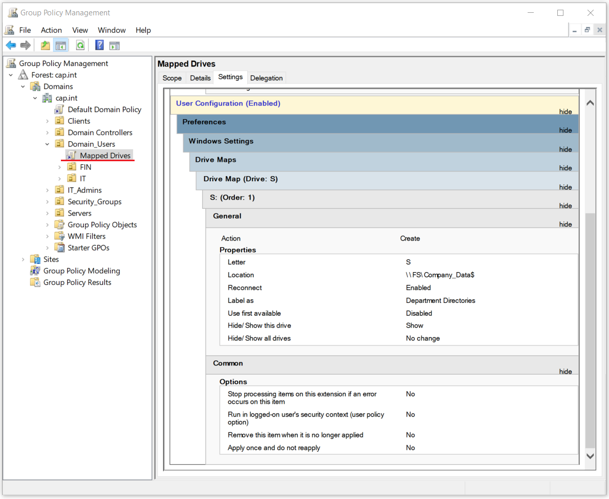
- Apply the Mapped Drives GPO to the OU Domain_Users
- Test the drive mapping by logging as a domain user such as amy.li on Thinkpad> Open PowerShell and run
gpupdate /force> logout
- Login as amy.li and wait for the GPO to be applied (the logon process will take ~3 minutes) and view the mapped drive and view the applied GPO with
gpresult /r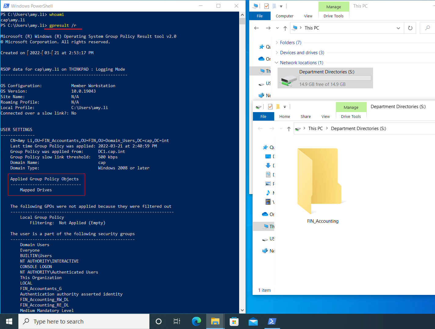
11.3 Create a Folder Redirection GPO
11.3 Create a Folder Redirection GPO
- From Failover Cluster Manager for FS-Cluster.cap.int > Roles > Select FS > Click Add File Share
- Complete the first 4 steps in the New Share Wizard to with the following:
- Profile: SMB Share Quick
- Location:
D:\HomeDir
- Share Name:
HomeDir$(remote path will be\\fs\HomeDir$
- On the step Permissions on the wizard set the following
- Disable inheritance > convert to objects
- Remove the principal Users with access = special
- Edit the principal Users > set the permission Applies to This folder only and check the advanced permission Create folders /append data
- Open Group Policy Management and create a GPO named “Folder Redirection” in the folder Group Policy Objects
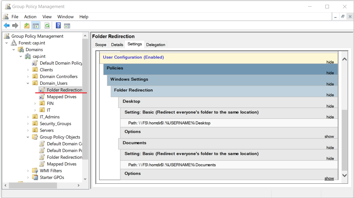
- Right-click the GPO > and click Edit
- From the editor navigate to User Configuration > Policies> Windows Settings > Folder Redirection
- Right click the folder Desktop > select Properties and set the following:
- Right click Desktop > Properties and edit as follows:
- Setting: Basic – Redirect everyone’s folder to the same location
- Target Folder Location: Create a folder for each user under the root path
- Root Path:
\\FS\\HomeDir$
- ❗ Should this GPO ever be deleted/removed, set the Target Folder Location to Redirect to the local userprofile location
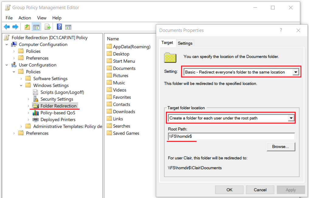
- Right click Desktop > Properties and edit as follows:
- Repeat on the Documents Folder
- Apply the GPO to the OU Domain_Users
- Test the drive mapping by logging as a domain user such as amy.li on Thinkpad> Open PowerShell and run
gpupdate /force> logout
- Login as amy.li and wait for the GPO to be applied (the logon process will take ~3 minutes) and the Desktop and Document folder properties and view the applied GPO with
gpresult /r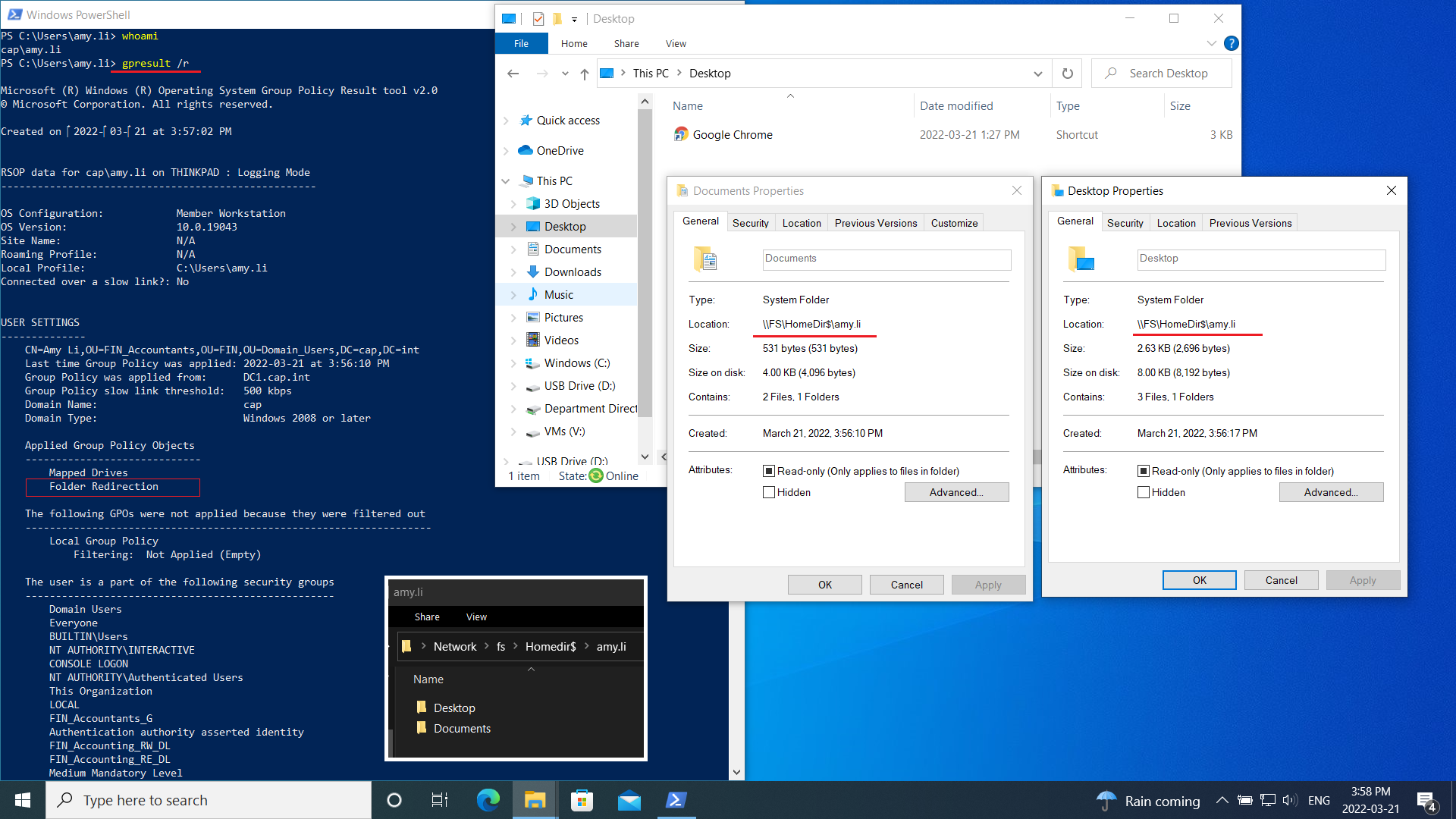
12.0 Create a secondary DC
Create a secondary domain controller DC2 that stores the data on a separate disk.
12.1 Create VM & Complete Post-Install Tasks
12.1 Create VM & Complete Post-Install Tasks
- ⏲❗ Checkpoint DC1 and name it “Before DC2”
- In Failover Cluster Manager for HV-Cluster create a new child differencing disk to ParentServer2019-core.vhdx parent
- Create a new VM named “DC2” with 1024 MB
- Complete all post install tasks and run script Appendix F with the following:
- $IP:
192.168.3.2
- $SrvName:
DC2
- $SrvOUPath:
OU=Servers,DC=cap,DC=int
- $IP:
- Verify all post-install tasks are complete and working as per Appendix G
- In ADUC manually move DC2 into the Domain Controllers OU
- Create a 2nd vhdx named “DC2db” that is 10 GB and dynamically expanding
- Attach DC2db.vhdx to the virtual machine DC2
- Add DC2 to Server Manager
- From Server Manager, bring the disk online, initialize, and create a volume
- From PowerShell on DC2 create the directories “NTDS” and “SYSVOL” on the secondary D:\ volume
12.2 Promote DC2 to Domain Controller
12.2 Promote DC2 to Domain Controller
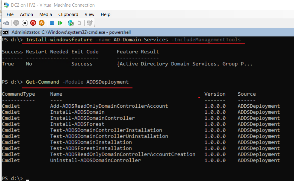
- From DC2’s PowerShell install ADDS then verify with the following:
Install-windowsfeature -name AD-Domain-Services -IncludeManagementTools
Get-Command -Module ADDSDeployment
- Enter the following script to promote to domain controller
#
# Windows PowerShell script for AD DS Deployment
#

Import-Module ADDSDeployment
Install-ADDSDomainController `
-NoGlobalCatalog:$false `
-CreateDnsDelegation:$false `
-Credential (Get-Credential) `
-CriticalReplicationOnly:$false `
-DatabasePath "D:\NTDS" `
-DomainName "cap.int" `
-InstallDns:$true `
-LogPath "D:\NTDS" `
-NoRebootOnCompletion:$false `
-SiteName "Default-First-Site-Name" `
-SysvolPath "D:\SYSVOL" `
-Force:$true
- From Server Manager, open Active Directory Sites an Services to view the replication
- Set DC2’s memory to 512 MB
Appendices
Appendix A: Network & IP Information
Appendix A: Network & IP Information
Networks
| Name | Network | Details | Subnet | Host IP Range | Switch Type |
|---|---|---|---|---|---|
| WAN | 192.168.1.0 /24 | Home Telus Network | 255.255.255.0 (/24) | 192.168.1.1 - 192.168.3.253 | External |
| LAN | 192.168.3.0 /28 | LAN | 255.255.255.240 (/28) | 192.168.3.1 - 192.168.3.14 | Internal |
| iSCSI | 192.168.10.0 /29 | iSCSI SAN | 255.255.255.248 (/29) | 192.168.10.1 - 192.168.10.6 | Private |
| HB | 192.168.20.0 /29 | Heartbeat | 255.255.255.248 (/29) | 192.168.20.1 - 192.168.20.6 | Private |
| LM | 192.168.30.0 /30 | Live Migration | 255.255.255.252 (/30) | 192.168.30.1 - 192.168.30.2 | Private |
IP Addresses & Info
| Name | IP | RAM | Notes |
|---|---|---|---|
| DC1 | 192.168.3.1 /28 | 512 | |
| DC2 | 192.168.3.2 /28 | 512 | |
| LinDHCP | 192.168.3.3 /28 | 512 | |
| SAN | 192.168.10.3 /29192.168.3.4 /28 | 512 | |
| HV1 | 192.168.10.1 /29192.168.20.1192.168.3.5 /28192.168.30.1 | 4096 | \\192.168.3.5\d$ (before CSV)
\\192.168.3.5\c$\ClusterStorage\Volume1\ |
| HV2 | 192.168.10.2 /29192.168.20.2192.168.3.6 /28192.168.30.2 | 4096 | \\192.168.3.6\d$ (before CSV)
\\192.168.3.6\c$\ClusterStorage\Volume1\ |
| HV-Cluster | 192.168.3.7 /28 | ||
| FILE1 | 192.168.20.3192.168.3.8 /28 | 512 | |
| FILE2 | 192.168.20.4192.168.3.9 /28 | 512 | |
| FS-Cluster | 192.168.3.10 /28 | ||
| FS | 192.168.3.11 /28 | \\fs\Company_Data$ \\fs\HomeDir$ | |
| Thinkpad (Host) | 192.168.1.74 /24192.168.3.13 /28 | 16 GB (Host) | |
| pfSense | 192.168.1.10 /24192.168.3.14 /28 | 512 |
Appendix B: Network Diagram
Appendix B: Network Diagram

Appendix C: CAP.INT Domain ADDS Diagram
Appendix C: CAP.INT Domain ADDS Diagram
Appendix D: Server File and Storage Diagram
Appendix D: Server File and Storage Diagram
Appendix E: VM Server 2019 Core Creation with Child Differencing Disk
Appendix E: VM Server 2019 Core Creation with Child Differencing Disk
- On the host Thinkpad and open PowerShell as an administrator and run the following:
#
# Create a VM with Windows Server 2019 (Core) with 2GB Static Memory on a Differencing Disk
# Connect to the LAN switch
# Disable automatic checkpoints & enable VM Guest Services
#
$VMName = Read-Host -Prompt 'Input the VM name'
$parentpath = "V:\VMs\VHDX\ParentServer2019-Core.vhdx"
$VHDPath = "V:\VMs\VHDX\" + $VMName + ".vhdx"

# Create VM with a differencing disk, update settings ,and start vm
New-VHD -ParentPath $parentpath -Path $VHDPath -Differencing
New-VM -Name $VMName -MemoryStartupBytes 2GB -VHDPath $VHDPath -Generation 2 -SwitchName LAN
Set-VM $VMName -AutomaticCheckpointsEnabled $false
Set-VMMemory $VMName -DynamicMemoryEnabled $false
Enable-VMIntegrationService -VMName $VMName -Name "Guest Service Interface"
Start-VM -Name $VMName
VMConnect.exe
- From the new VM console, enter in the default admin password as
Pa$$w0rd
Appendix F: Server Post-Install PS Script
Appendix F: Server Post-Install PS Script
- Complete the post installation tasks from the new VM with
PowerShellwith the following script:❗ This script is set up for Proj.int
192.168.3.0/ 28# # Post-installation tasks # $IP = Read-Host -Prompt 'Enter IP 192.168.3.x' $SrvName = Read-Host -Prompt 'EnterServerNAME' $SrvOUPath = Read-Host -Prompt 'AD Path OU=X,OU=Servers,DC=cap,DC=int' $MaskBits = 28 $Gateway = "192.168.3.14" $Dns = "192.168.3.1" $IPType = "IPv4" # Retrieve the network adapter that you want to configure $adapter = Get-NetAdapter | ? {$_.Status -eq "up"} # Remove any existing IP, gateway from our ipv4 adapter If (($adapter | Get-NetIPConfiguration).IPv4Address.IPAddress) { $adapter | Remove-NetIPAddress -AddressFamily $IPType -Confirm:$false } If (($adapter | Get-NetIPConfiguration).Ipv4DefaultGateway) { $adapter | Remove-NetRoute -AddressFamily $IPType -Confirm:$false } # Configure the IP address and default gateway $adapter | New-NetIPAddress ` -AddressFamily $IPType ` -IPAddress $IP ` -PrefixLength $MaskBits ` -DefaultGateway $Gateway # Configure the DNS client server IP addresses $adapter | Set-DnsClientServerAddress -ServerAddresses $DNS # Rename the Network Adapter Rename-NetAdapter -Name "Ethernet" -NewName "LAN" # Name Computer, add to Domain and OU placement $cred = Get-Credential cap\aidan Add-Computer -DomainName cap.int -Credential $cred -OUPath $SrvOUPath $computer = Get-WmiObject win32_computersystem $r = $computer.rename("$SrvName", $cred.GetNetworkCredential().Password, $cred.username) #Rename the local admin account Rename-LocalUser -Name "Administrator" -NewName "_lsysadmin" # Restart-Computer -Force
Appendix G: Server Post-Install Verification Checklist
Appendix G: Server Post-Install Verification Checklist
- Login to the virtal machine using the domain admin account cap\aidan
- Complete the following in PowerShell
whoami: verify server is a domain member and that the admin aidan@cap.int is logged in
ipconfig: verify IPv4 address, subnet, default gateway
tracert google.ca: verify internet connectivity and DNS
ping LinDHCP: test DNS to a domain server
Get-LocalUser: verify the local admin account has been renamed to _lsysadmin
Get-NetAdapter: verify the network adapter has been renamed
- From
sconfig(Server Configuration) complete the following options:11Windows Activation, verify Windows is activated and has the 180 day trial
6Download and Install updates
- From Server Manager view the new entry in DNS Manager and ADUC
- Add the new VM to Server Manager
- ⏲ Checkpoint (optional)
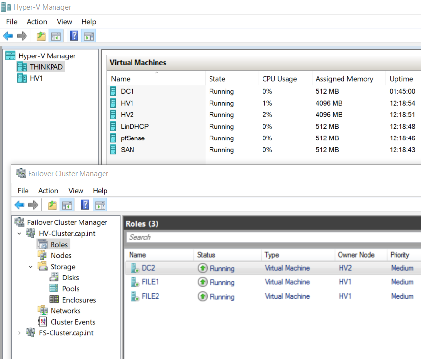
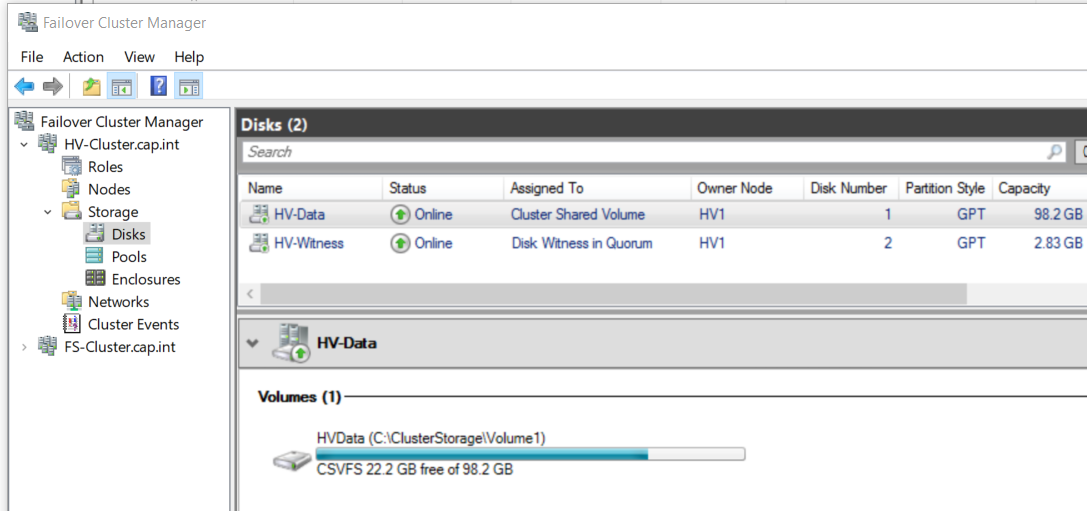
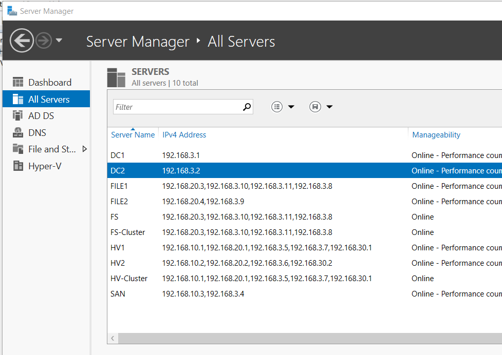
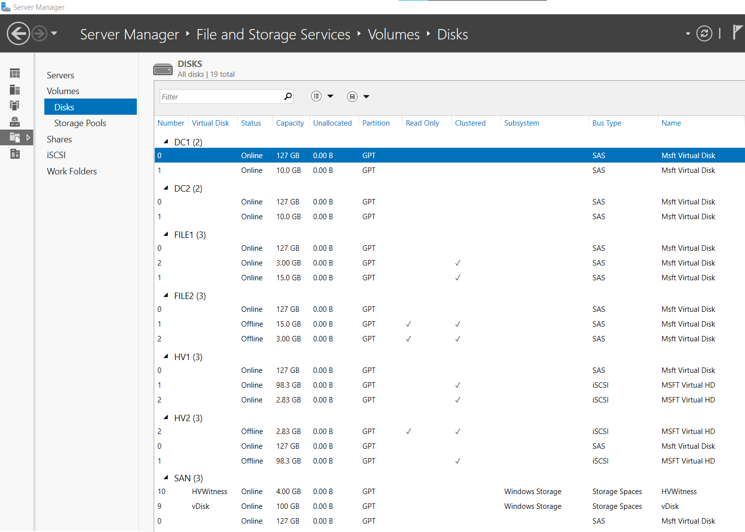
Appendix H: Final Setup Screenshots
Appendix H: Final Setup Screenshots
Appendix I: References
Appendix I: References
pfSense - NAT & Firewall
Linux CentOS 8 DHCP
Nested Hyper-V Failover Cluster, Jumbo Frames, Cluster Shared Volume
VHD Set